Resources - Taxonomy - Structure (Software)
The Taxonomy - Structure (Software) aspect of the Resources view helps UAF Architect to describe the software components of the enterprise.
Describing Software components - Application Systems
Describing an Application System with HOPEX UAF
Accessing Application Systems with HOPEX UAF
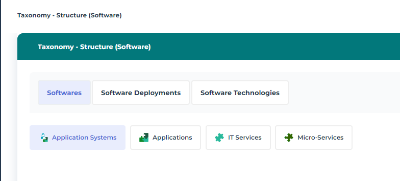
To access Application Systems:
1. From the navigation menu, select Resources > Taxonomy - Structure (Software).
2. Click the Software tab.
3. Click the Application System sub-tab.
The list of Application Systems of the Enterprise is displayed.
Application Systems diagrams with HOPEX UAF
An application system is described by several types of diagrams:
• A Sketching diagram is used to enables you to draw diagrams freehand and connect the shapes to objects of the repository using High Level Operational Concept.
• An Application System Deployment Architecture is used to represent the technical architecture chosen for the deployment of each component that support the application system as well as the techniques used for their communications .
• An External Data Flows diagram describing external data flows of an application system in a given environment. It contains the subject application system and application flows exchanged with partners (other application systems, applications, data stores, org-units or position type.
• An External Interaction diagram describing external service interactions of an application system in a given environment. It contains the subject application system and its interactions with partners (other application systems, org-units or position types).
• An Internal Architecture diagram displaying the first level components of an application system, the access points (service/request points) and the connections between the components.
• An Internal Data Flows diagram describing internal data flows of an application system. It contains the agents necessary for the scenario (application systems, applications, microservices, data stores, org-units or position types) and exchanged application flows.
Application Systems Properties
The Characteristics property page for an application system provides access to several sections.
• The Identification section provides access to the following information:
• the Name,
• its Owner, by default during creation of the application system, the current library.
• the text of its Description.
• the internal Code,
• the Version number,
• Description.
• About the Functional Scope section of the application system, see Defining Application Functional Scope.
• The Responsibility section relates to the person(s) responsible for the application system.
• Software Designer
• Local Application Owner
• The Attachments section is limited to associated attachments.
With HOPEX IT Architecture an application system is described by other property pages. See HOPEX IT Architecture properties pages content.
Creating an application system structure diagram
This diagram describes the internal structure of an application system:
• services offered or required,
• the application components and their interactions; these are application systems service, applications and microservices,
• the end users interacting with the application components.
The following diagram describes the application system corresponding to purchasing requests processing.
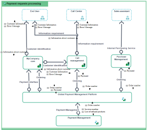
The following diagram describes the application system corresponding to purchasing requests processing.
To create an application system structure diagram:
1. Open the Diagrams page of the application system of your choice and click Create a diagram.
2. Select Structured diagram > Internal Architecture.
The application system structure diagram appears.
Adding an application system to an application system structure diagram
To describe an application system that implements another application system, you can add an application system of the application system structure diagram.
For example, the purchasing requests processing system uses the "Purchasing Management Platform" and "Payment Management" application system services.
To add an Application System:
1. In the objects toolbar of the application system structure diagram, click  Application System.
Application System.2. Click in the frame of the described application system.
An addition window box prompts you to choose the application system implemented (for example "Payment management").
3. Select an application system.
4. Click OK.
The application system appears in the diagram.
Adding an end user to an application system structure diagram
To specify that an application system, such as purchasing request processing, is activated by internal or external org-units, you will add an associated end user.
To add an end user:
1. In the application system structure diagram objects toolbar, click  End User and click in the frame of the diagram.
End User and click in the frame of the diagram.An addition window prompts you to choose the Object Type that you wish to use: Org-Unit or Position type.
2. For example, select the Org-unit object type.
3. Select the org-unit that interests you and click OK.
The actor appears in the diagram.
Describing an application system environment with HOPEX UAF
Creating an application system environment
To create an Application System Environment from the Application Systems navigation menu:
1. Open the Environments page of the application system of your choice.
The list of application system environments appears in the edit area.
2. Click New.
The new application system environment appears in the list, it has the name of the application system followed by "Environment".
Application system environment properties
The Characteristics properties page for an application system environment provides access to:
• its Owner, by default during creation of an application system environment, the current library.
• its Name,
• the text of its Description.
With HOPEX UAF an application system environment is described by other property pages. See HOPEX IT Architecture properties pages content.
Application system environment diagrams
An application system environment is described by several types of diagram:
• an Application System Environment diagram describes the exchanges between the subject application system and its partners in a specific context.
• a scenario of application system environment flows presents the flows exchanged between the application services or the microservices used by the described application system in a specific context.
Describing an application system environment diagram
An application system environment is described by an application system environment diagram that describes the service interactions between the internal application systems, its users and the partner application systems.
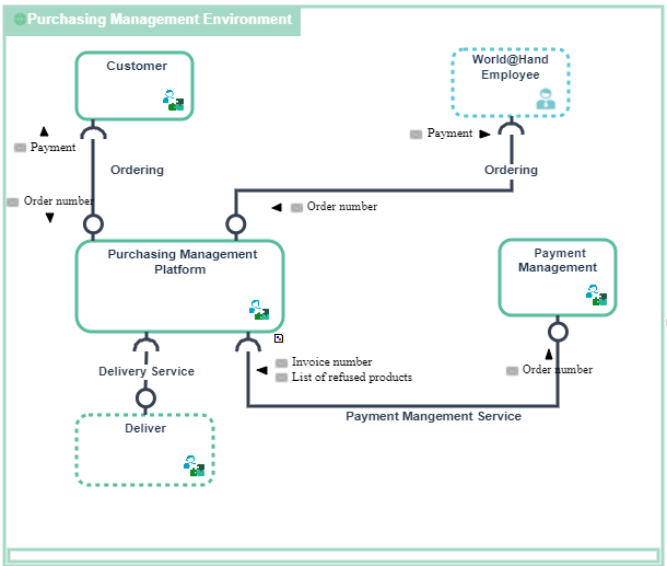
Application system environment diagram for the Purchasing Requests
Purchase requests are formulated by clients or employed using the "Purchasing Management Platform".
The "Purchasing Management Platform” application system uses an internal application system for the “Payment management” and a partner application system for the “Delivery”.
The elements of an application system environment diagram are:
• the main application system principal described by the environment.
• partner application systems that represent the other application system with which the main application system described by the environment interacts.
In this example, this concerns two loan services offered to individuals and companies.
• The categories of users of services provided by the environment are represented either by an Org-Unit or by a Position Type.
This concerns two user categories: individuals and companies.
• Service interactions between components
Describing Software components - Applications
Describing an Application with HOPEX UAF
Accessing Applications with HOPEX UAF
To access Applications:
1. From the navigation menu, select Resources > Taxonomy - Structure (Software).
2. Click the Software tab.
3. Click the Applications sub-tab.
The list of Application of the Enterprise is displayed.
Application diagrams with HOPEX UAF
An application is described by several types of diagrams:
• A Sketching diagram is used to enables you to draw diagrams freehand and connect the shapes to objects of the repository using High Level Operational Concept.
• An Application Deployment Architecture is used to represent the technical architecture chosen for the deployment of each component that support the application as well as the techniques used for their communications .
• An External Data Flows diagram describing external data flows of an application system in a given environment. It contains the subject application system and application flows exchanged with partners (other application systems, applications, data stores, org-units or position type.
• An External Interaction diagram describing external service interactions of an application system in a given environment. It contains the subject application system and its interactions with partners (other application systems, org-units or position types).
• An Internal Architecture diagram displaying the first level components of an application, the access points (service/request points) and the connections between the components.
• An Internal Data Flows diagram describing internal data flows of an application. It contains the agents necessary for the scenario (application systems, applications, microservices, data stores, org-units or position types) and exchanged application flows.
Describing an Application Environment with HOPEX UAF
An application environment is described by several types of diagrams:
• a scenario of application environment flows describes the flows exchanged between the described application and its partners: applications, application systems, IT services or microservices used by the described application in a specific context.
• a scenario of sequences of flows presents the agents necessary for the scenario (application, IT services, microservices, data stores) and sequence application flows exchanged.
To create an Application environment:
1. Open the Environments page from the application of you interest.
The list of application environments appears in the edit area.
2. Click New.
The new application environment appears in the list under the name “Environment” followed by the name of the application.
To access the list of application environments from the Applications navigation menu:
The list of application environments appears in the edit area.
Application Environment Diagram presentation
With HOPEX UAF, an application environment is entirely described by a an application environment diagram that is used to describe the service interactions between the environment applications described, its users and the external applications.
An application environment diagram includes:
• applications that represent the environment described.
In the example, this concerns the applications used for buying spare parts.
• applications, application services or partner microservices that represent the external elements used in the described environment.
This example concerns automated Web services.
• Service interactions between components.
• request and service points.
The Components property page of the application environment provides access to partners elements: Applications, Microservices, IT Services, System users.
Describing Software components - IT Services and Microservices
Describing an IT Service with HOPEX UAF
Accessing IT Services with HOPEX UAF
To access IT Services:
1. From the navigation menu, select Resources > Taxonomy - Structure (Software).
2. Click the Software tab.
3. Click the IT Services sub-tab.
The list of IT Services of the Enterprise is displayed.
IT Service diagrams with HOPEX UAF
An IT Service is described by several types of diagrams:
• An Internal Architecture diagram displaying the first level components of an IT Service, the access points (service/request points) and the connections between the components.
• An Internal Data Flows diagram presents the flows exchanged between the described IT services or microservices. A scenario can represent a particular use case of the IT service or more globally all the flows exchanged within this IT service.
Describing a Microservice with HOPEX UAF
Accessing Microservices with HOPEX UAF
To access Microservices:
1. From the navigation menu, select Resources > Taxonomy - Structure (Software).
2. Click the Software tab.
3. Click the Microservices sub-tab.
The list of Microservices of the Enterprise is displayed.
Microservice diagrams with HOPEX UAF
A Microservice is described by several types of diagrams:
• A Sketching diagram is used to enables you to draw diagrams freehand and connect the shapes to objects of the repository using High Level Operational Concept.
• An Microservice Deployment Architecture is used to represent the technical architecture chosen for the deployment of each component that support the microservice as well as the techniques used for their communications .
• An Internal Architecture diagram displaying the first level components of a microservice, the access points (service/request points) and the connections between the components.
• An Internal Data Flows diagram presents the flows exchanged between the microservice elements in a given context.