Presenting the Method and Example
The specification of IS upgrade projects with HOPEX Application Design contains the following steps:
Example Overview
These different points of view are illustrated by the example of a boat rental enterprise that has decided to improve its purchasing process.
Availability of boats being a vital element of company activity, a specific process must be defined to process urgent purchases for boat maintenance and repair.
Company purchasing processes are split between operational purchase processes and investment purchase processes. Operational purchasing processes include purchase of spare parts and raw materials required for boat maintenance and repair.
Organizational Context
The purpose of the new organizational process for processing urgent purchase requests is to increase responsibilities of the purchasing assistant, so as to be able to send purchase orders at very short notice.

"Process Urgent Purchase Request" Organizational Process
The purchasing assistant begins by analyzing the purchase request. If the amount is large, the normal process purchase request process is implemented.
If the product is available, the assistant sends the availability request.
If not, the assistant sends a purchase order to the supplier. The rest of the processing is carried out within the framework of the normal "Process Purchase Request" organizational process.
To allow the purchasing assistant to rapidly analyze the purchase request and send the order, he/she is provided with a new application enabling access to data concerning stock and suppliers.
Describing a Project and its Environment
The project is the basic element used by HOPEX Application Design.
An Enterprise Architecture project is a part of a system whose study is entrusted to a single team, which transforms a system or part of a system to achieve a given objective.
To describe the scope of the project , you must:
• describe the project applications and their exchanges
• describe the project deliverables
With HOPEX Application Design, you can also define the different organizations concerned by the project.
Describing the project applications and their exchanges
An application environment is used to represent a use context of an application.
With HOPEX Application Design, you can use flow scenario diagrams to describe the flows exchanged by an application, an application service or a micro service in a particular context.
The diagram below describes the flows exchanged in the context of the "Purchasing Management System" application.
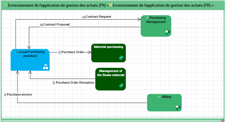
Equipment purchases for boat maintenance are made directly by the Representation Office, using an "Equipment Purchasing" application service. This calls a "Purchase Management" application located centrally at Headquarters.
If the purchase involves a new type of equipment or a new supplier, a contract request is sent to the supplier using the application at Headquarters. The supplier returns a contract proposal which is submitted to the requester.
In the other cases, a representative from the Representation Office sends a purchase order to the supplier using the "Equipment Purchasing" application.
Reception of purchases is handled by the "Boat Inventory Management" application at the Representation Office.
The invoice is managed in the "Billing" application at Headquarters.
Describing the project deliverables
After analysis, the application elements that will be allocated by the project are described in the project deliverables.
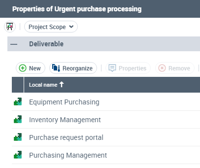
The "Equipment Purchasing" application is the main application impacted by the project, in particular for improvement of its access portal.
The "Stock Management" application is used by the "Inventory Management" application to view and update information on stock and in particular, spare parts.
The "Purchasing Management" application uses the "Catalog" database to send a purchase order.
The "Maintenance and Repair Management" and the "Spare Parts Management" applications also use the "Equipment Purchasing" application portal.
For more details on how to describe a project environment, see "Describing an AD Project and its Application Environment", page 29.
Describing the Objectives and Requirements for a Project
To refine the description of the technical scope of a project, this step consists of defining the goals and the requirements of the different categories of users.
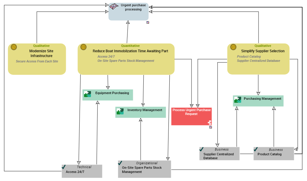
In our example, the development of an application supporting the processing of urgent purchase requests has several objectives:
From a functional viewpoint, this application must ensure reduction in boat immobilization time due to a spare part requirement. Purchase request processing must therefore be accessible 24 hours a day, since company representation offices are spread over several continents, and 7 days a week since the company activity is leisure and tourism.
To reduce delays in the search for suppliers of spare parts already referenced or not, the purchasing department has decided to set up a product catalog and a centralized supplier database.
The project also meets a technical objective, which is to modernize and improve security of communications between company headquarters and the representation offices.
The objective and requirement diagram of a project is used to represent and classify the elements listed.
For more details on managing objectives and requirements, see "Defining the Objectives and Requirements of a Project (AD)", page 41.
Building Functional Specifications
After defining the project scope, objectives and requirements, this step consists of describing the functionalities expected of the future system by the different categories of users.
Describing the map for the expected functionalities of the project
A functionality map is a set of functionalities with their dependencies that, jointly, define the scope of a hardware or software architecture.
A description of the functionality map is used to draw up the list of expected functionalities of the project and associate each of them with an objective or requirement, on the one hand, and an application element, on the other hand.
In our example, a functionalities map is presented in the form of the following diagram.
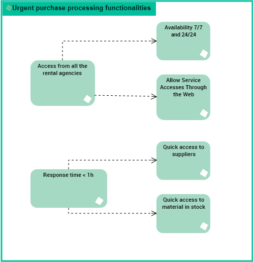
The expected functionalities of the project for processing urgent purchases are relative to the response times and to the availability of the application from the rental agencies. The main functionalities are divided into sub-functionalities.
Describing the application environments of the project
An application environment presents the use context of the applications of a project. This describes the interactions between the org-units involved and the internal and external applications of the projects that ensure the project functionalities.
A number of diagram types are offered to describe an application environment:
• The flow scenario diagram for application environments is used to describe the flows exchanged between an application and it environment in a given context.
• The application environment diagram is used to describe the interactions between an application and its described environment: its users, the applications and the external users.
• The use case diagram for application environments is used to describe the use cases of the application environment in UML format.
Flow scenario diagram example
A flow scenario diagram can be built for an application environment, an application, an application service or a micro-service.
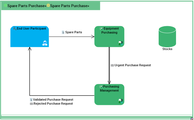
This flow scenario diagram describes the "Spare Parts Purchasing" application.
The "spare part" request is sent by the local Purchasing assistant to the "Equipment Purchasing" application.
The "Equipment Purchasing" application checks the stock. If the part is not in stock, an "urgent purchasing request is sent" to the "Purchasing Management" application.
The "Purchasing Management" application validates or refuses the request.
Example of a Use Case Diagram
You can also use a use case diagram to describe the interactions between an application element and the org-units in the specific context.
The use case diagrams can be built for the application environments, application services and micro-services.
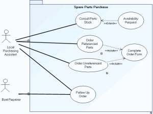
The system is used to consult parts in stock and to order new spare parts.
Consultation of parts in stock is carried out by the local on-site purchasing assistant. Following consultation, the assistant can make an availability request.
Two order types are possible, one for parts already referenced, the other for parts as yet unreferenced. In both cases, an order form should be completed.
Order follow-up is assured by the local purchasing assistant and the boat repairer.
Application environment diagram example
The following diagram describes the application environment corresponding to the processing of spare parts purchasing.
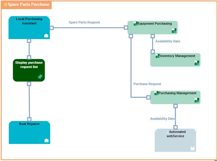
"Spare Parts Purchase" application environment diagram
The requests for spare parts are formulated by the persons concerned with boat repairs and these requests are processed by the local purchasing assistants.
Consultation of parts in stock is carried out by the local on-site purchasing assistant. Following consultation, the assistant can make an availability request.
Two order types are possible, one for parts already referenced, the other for parts as yet unreferenced. In both cases, a request for availability is put forth.
Order follow-up is ensured by the local purchasing assistant and the boat repairer.
For more details on functional specifications, see "Describing the Functional Specifications of a Project", page 51.
Describing the Project Data
The purpose of this step is to describe the data domains to deduce the database structures that will be implemented by the project.
To successfully complete this step, perform the following tasks:
Specifying packages
The package allows you to classify elements referenced in a project. You can create sub-packages in a package to classify objects in finer detail, for example actors of a project.

Urgent purchase requests are provided to process purchase of spare parts and boat rental requests. In both of these cases, users are actors of the purchasing domain.
Specifying logical data areas
A logical data area is used to define a logical data structure made up of classes and data views.
A logical data domain is owned by a package and can reference objects held in other packages.
During integration, a corresponding physical structure can be defined via a physical data area. It is made up of tables and table views.
The following logical data area diagram represents a data structure relative to the Orders.
Specifying relational data areas
A relational data area is used to position the databases in the database management logical model.
The relational data model of the "Purchase Request Automation" project is presented below.
 The application manages purchase requests, orders and product stock levels in each of the representation offices.
 A centralized catalog of products and suppliers is installed.
Contracts with referenced suppliers are also accessible using the application.
For more details on describing data, see "Describing the Data of a Project", page 65.
Building the System Specifications
After the functional specifications and the description of data used, the technical specifications of the project aim to detail the target architecture of the project.
Describing the target architecture elements
After the functional specifications and the description of data used, the technical specifications of the project aim to describe the target architecture of the project components: applications, application services, micro-services, databases.
Application process presentation
An application process is used to describe the detailed sequence of tasks completed on execution of the application.
The following system process diagram proposes a first draft of operation expected of the new application.

A product search is carried out from the referenced products repository.
If the product is referenced, stock is analyzed.
If stock is sufficient, a "Make available" request is activated and the process ends.
If stock is less than minimum stock, a purchase order is sent to the supplier.
If the product is new, search for a supplier and comparative study of prices is carried out. An order is then sent and the process ends.
Describing batch processing
The sequencing of automated processes can be described in a batch planning structure diagram.
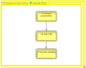
Describing the list of services and interfaces
It is possible to describe interfaces connecting services or operations with the exterior. This description is carried out in a user interface diagram.
An interface diagram is used to describe the planned interfaces.
For more details on technical specifications, see "Describing the Technical Specifications of a Project", page 77.