Describing Application Processes
In detailed specification phase, the progress of tasks implemented in an IT service can also be modeled by a system process. More generally, operation of an architecture element can be described by a system process modeling, for example, sequence flow of screens presented to the user.
System Process example
The diagram below represents purchasing requests processing.
• The final user send information about him/her via "MyCompagny.com” application.
• A customer search is carried out by the application from the Clients data base.
• This error message is returned if the customer is not found.
• If the customer is found, the "Purchasing Management Platform” updates the shopping cart and the order validation is activated.
• The "Validate the order” task activates "Payment management” application for “Order pavements”. The invoice number is sent back to the "Purchasing Management Platform” for billing
• The “Create invoice” task updates the payments database and the process ends.

Application process diagram
Prerequisite
You must first define a work environment for a project in progress. See "Le volet Projet en cours", page 22.
Managing System Processes with HOPEX Application Design
Accessing system processes
To access the list of system processes using the Current Design Project navigation pane:
1. Select Application Architecture Design.
2. Select the System Processes tile.
The list of system processes appears.
Creating a system process diagram
To create a system process diagram:
The diagram opens in the edit area.
Modeling Tasks of a System Process
The functional analysis phase of the project is based on use cases and on the data model, obtained in preliminary study phase, to represent the functional architecture of the future system.
The functional analysis phase describes the system processes implemented in the different use cases of an application or service.
A system process diagram specifies the sequence flow of tasks to be executed so that the user can check that the application satisfies its requirement.
Describing a Use Case by a System Process
To create a system process from a use case:
1. Right-click the use case to open its pop-up menu.
2. Select New > System Process.
The diagram of a new system process opens. The system process associated with the use case is already positioned in the diagram.
Functional Modeling Example
The system processes used for a project functional analysis are stored in a package.
In the example of the purchase request processing automation project, system processes are stored in the "Urgent Purchase Requests" package .
Access the system process diagram from a package
To access the system process diagram from a package:
1. In the Home navigation window, expand the tree associated with the package, for example the "Urgent Purchase Requests" package.
The list of system processes stored in the package appears.
2. Right-click the system process, for example "Urgent Order Interface" to open its pop-up menu, and select System Process Diagram.
The diagram opens.
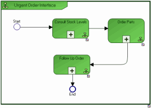
The main steps of this system process are:
consult local stock levels so that a spare part can be made available
order parts when stock level has reached critical threshold or if a part is unreferenced
follow-up an order
Display the diagram describing a step in the system process in detail:
To open the diagram describing a step in the system process in detail:
1. Right-click the system process, for example "Consult Stock Levels" to open its pop-up menu.
2. Select System Process Diagram.
The diagram associated with the process opens.

Consulting stock levels begins by display of a screen enabling identification of the required part. The list of parts found in the catalog is presented in the next screen.
When the user has selected the required part, information on details is displayed. From this screen, it is possible to obtain information on another part, make an availability request for the part, or indeed order the part.
Modeling Tasks of an IT Service
The phase of detailed analysis of system components impacted by the project consists of detailed modeling of the operation of IT services.
In the context of the urgent order request processing automation example, the service for comparing prices is represented by a system process.

This diagram describes the algorithm of the "Compare Prices" service, which should return the reference of the lowest-priced part.
The list of suppliers of the required part is given at input. The part proposed by the first supplier in this list becomes the reference part. Assuming the supplier list is not empty, data concerning the required part is then analyzed. If the price of the current part is lower than the price of the reference part, the reference part becomes the current part.
When the complete list of suppliers has been analyzed, information concerning the reference part is sent to the "Order Amount Calculation" service.