Using IT architecture diagrams
With Hopex IT Architecture, an application object may be described by different diagrams. Each diagram type corresponds to a specific view of the object: internal architecture, deployment architecture, flows exchanged inside the object and flows exchanged outside depending on the context of use of the object. Depending on the described object, each representation is associated to a diagram type.
• External data flows are represented in an Environment Diagram. This diagram type contains the described application object and the application flows exchanged with partners (other application systems, applications, data stores, org-units or
position type).
position type).
• The internal architecture is described by a structure diagram representing the object components their exchanges. A structure diagram can be designed for an application, an application environment, an application system, an application system environment, a logical application system, a logical application, an application service or a microservice.
• The deployment architecture is described by a diagram representing the deployable application packages, the microservices and the deployable data package used as well as the required communication techniques.
• The Internal Data Flows are represented in a scenario of flow diagram describing the messages exchanged between the object components. With Hopex IT Architecture, you can design two types of scenario of flow diagram:
• The Scenario of flows diagrams that describe the flows exchanged in different use scenarios of the object described.
• Scenario of sequence diagrams that describe the chronology of the flows exchanged in different use scenarios of the object described.
• The external interactions are represented in a Scenario of Flow Diagram describing the external service interactions of an application object in a specific environment. This diagram contains the described object and the service interactions with partners (other systems).
|
Representation
|
List of involved diagrams
|
|---|---|
|
Internal Architecture
|
• Application structure diagram
• Architecture
• Application System Structure Diagram
• IT Service Structure Diagram
• Microservice structure diagram
• Application System Structure Diagram
• Logical application structure diagram
• Structure diagram of the logical application system
• Deployable Application Package Diagram
• Resource Architecture Assembly Diagram
• Hardware Assembly Diagram
• IoT Device Assembly Diagram
|
|
Internal Data Flows
|
• Scenario of Application Flow Diagram
• Scenario of Application System Flows Diagram
• Scenario of IT Service Flow Diagram
• Scenario of Microsystem Flows Diagram
• Scenario of Logical Application System Flows Diagram
• Scenario of Application Flows Sequence Diagram (UML)
• Scenario of Application System Flows Sequence Diagram (UML)
|
|
External Data Flows
|
• Scenario of Application Environment Flows Diagram
• Scenario of Application System Environment Flows Diagram
• Scenario of Logical Application System Environment Flows Diagram
• Scenario of Application Environment Flows Sequence Diagram (UML)
• Scenario of Application System Flows Sequence Diagram (UML)
|
|
External Interactions
|
• Application Environment Diagram
• Application system environment diagram
• Logical application system environment diagram
• Resource Architecture Environment Diagram
|
|
Deployment Architecture
|
• Application Deployment Architecture Diagram
• Application System Deployment Architecture Diagram
• Microservice Deployment Architecture Diagram
|
Creating a structure diagram
To create a, Application system structure diagram, for example:
1. Open the Diagrams property page of the application system and click Create a diagram.
2. In the choice window, select Structured diagram > Internal Architecture.
The diagram opens in the edit area. You are now in the Hopex graphic editor. The frame of the described object appears in the diagram.
Example of an application system structured diagram
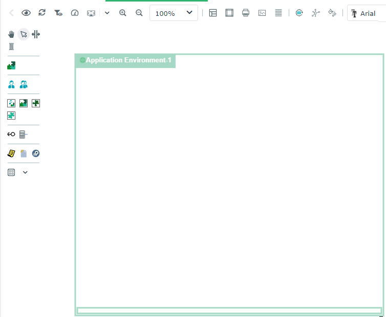
Diagram commands with Hopex IT Architecture


Auto Layout in architecture diagrams
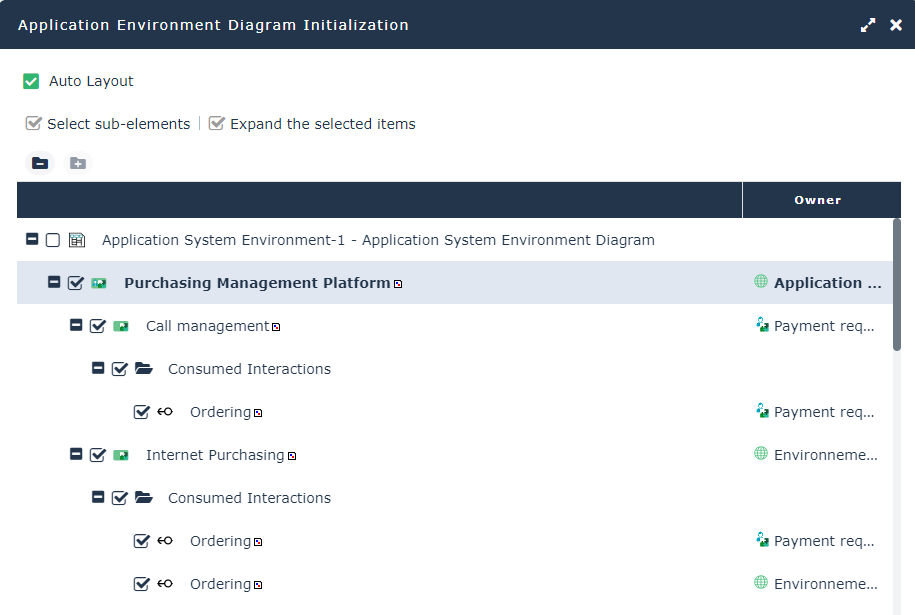
Environment diagram initialization
Creating a Sketching diagram with Hopex IT Architecture
Creating an ArchiMate@ diagram with Hopex IT Architecture
Hopex for the ArchiMate® Framework product provides facilities to use the set of concepts defined by the Open Group for ArchiMate®. ArchiMate® concepts are mapped with Hopex Enterprise Architecture building blocks so as to manage compatibility and continuity with other models.
You can associate a diagram based on ArchiMate@ formalism to an application, for example.
Using diagram comparison
The comparison of diagrams of an application system or architecture of an application system deployment enables to compare different versions of the same object.