Using a Scenario of Application Flows Diagram
The scenario of flows diagram describes the flows exchanged between the system elements represented.
Two types of diagrams are proposed:
• The Scenario of flows diagrams that describe the flows exchanged in different use scenarios of the object described.
• Scenario of sequence diagrams that describe the chronology of the flows exchanged in different use scenarios of the object described.

To use Scenario of Application Flows Diagrams, open the
Options window and check that
Hopex Solutions > IT Architecture > Architecture Modeling > Activate Flow Scenario Sequence Diagrams option is activated.
A Scenario of Application Flows Diagram can be built for:
• an application environment,
• an application,
• an application system,
• an IT service, or
• a microservice.
This diagram is used to describe the exchanges inside the described object in a specific context.
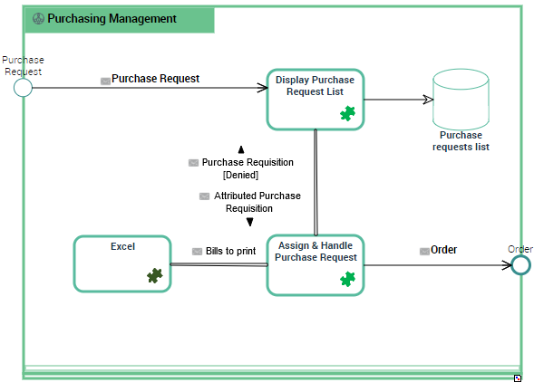
Example of a Scenario of Application Flows for "Managing Purchase Orders".
In a scenario of application flows diagram, the elements represented are:
The interactions offered between these elements:
• application flows connected to flows,
• application flow channels that group a number of application flows on a single link,
• application data channels that represent the interactions between the application data stores.
Creating a Scenario of Application Flows diagram
To create a scenario of application flows:
1. Go to the list of applications and click the icon Create a diagram for the application of interest.
2. Select Structured diagram > Internal Architecture and click Create this diagram.
3. Choose Internal Flows.
The Scenario of Application Flows Diagram appears.
Adding an IT service to the scenario of application flows

An IT service is a software component of an application, that can't be deployed alone and that realizes a sub-set of the functionalities of this application either for end users of this application or inside the application (or another application). This includes batch programs.
To add an IT service:
1. In the objects toolbar of the scenario of application flows, click IT Service.
2. Click in the described application frame.
An addition window box prompts you to choose the IT Service implemented (for example "Customer management").
3. Select the IT Service required and click OK.
The IT Service appears in the diagram.
You can add a microservice in the same way.
A microservice is a software component that can be deployed autonomously, but which does not directly provide an end user service. It can interact with other application services, applications or application systems. This is a deployable software component that uses software technologies. For example: an authentication service, a PDF file printing service.
Creating an Application Flow
An application flow represents the use of a flow between two agents (e.g., applications) in a usage context (represented by a scenario of flows). An application flow is based on a flow, which represents the reference flow in context.
The application flows exchanged between IT services, microservices, or application ports in a scenario of application flows are associated with a flow, which is itself associated to a communication system and a content.
A flow represents the circulation of information between two agents in the Information System (for example, two applications, an application and an actor, etc.). This flow is defined by a sender, a receiver, and exchanged content, symbolizing the data being transported. A flow is defined in absolute terms.
The content designates the content of a message or an event, independent of its structure. This structure is represented by an XML schema linked to the content. A content may be used by several messages, since it is not associated with a sender and a destination. There can be only one content per message or event, but the same content can be used by several messages or events.
When creating an application flow, you must associate it with a communication system and a content.
To create an application flow:
1. In the objects toolbar of the scenario of application flows, click Application flow and select the Type of application flow that interests you.
• Result/Provision associated to a service result,
• Call/Request associated to a service request,
• Signal associated to an information exchange.
2. Click the first object representing the sender of the flow and, holding the mouse button pressed, draw a link to the object receiving the flow.
The Application Flow Creation dialog box opens.
3. Select the communication system that will be associated to the flow.
4. From the Content field, select the content you wish to associate with the message flow.
5. Click OK.
If it doesn't exist yet, a flow is created.
The application flow, represented by an arrow between the sender and the receiver, is displayed in the diagram. By default, the name of the flow is displayed on the link.
To display the
Content and the
Flow on the
application flow link, click the application flow to display its contextual menu and select
Shapes and Details. From the
Flow folder, check the
Short Name Content box.
Accessing Application Flow Properties
An application flow represents the use of a flow between two agents (e.g., applications) in a usage context (represented by a scenario of flows). An application flow is based on a flow, which represents the reference flow in context.
To access an Application Flow properties from a scenario of application flows diagram:
1. Select the link connected to the application flow that interests you:
The application flow properties open to the right of the diagram.
2. In the Characteristics page, the Flow field enables the access to the associated Flow properties.
3. In the Diagrams page, enables the access or the creation of a Communication Chain diagram associated to the Flow.
Accessing a flow properties
You can access a flow properties from the application flow that references it or from a scenario of flow diagram.
A flow represents the circulation of information between two agents in the Information System (for example, two applications, an application and an actor, etc.). This flow is defined by a sender, a receiver, and exchanged content, symbolizing the data being transported. A flow is defined in absolute terms.
To access a flow from a scenario of application flows diagram:

From the link of the application flow, click the flow name that interests you.
The flow properties open to the right of the diagram.
• The Characteristics page provides access to the following sections:
• Identification, presenting the Name of the flow, its Description, the Application flow type and the flow Code.
• Implementing software, presenting the Communication system owned by the flow as well as the application communication chain.
A flow can be linked to several application communication chains.
• Qualification, presenting the Flow Measures defined for the flow.
• The Usage page provides the list of application flows connected to the flow.
• The Service Interface used page provides access to the interfaces and operation services used by flows.
• The Diagrams page enables the access or the creation of a Communication Chain diagram associated to the Flow.
Creating an application flow channel
An application flow channel is used to graphically group a number of application flows into a single flow.
To create an application flow channel, you must first create the channel and then link the application flows that it groups.
To create an application flow channel:
1. In the objects toolbar of the scenario of application flows, click Application Flow Channel.
2. Click the first object in communication and, holding the mouse button pressed, draw a link to the other object.
The application flow channel appears in the diagram.
To connect the application flows to the application flow channel:
1. Open the Characteristics page of the application flow channel.
2. In the Grouped Flow section, click Connect.
A selection dialog box opens and presents the list of the application flows of the scenario of application system flows.
3. Select the flows that you want to group and click OK.
The content of the selected flows is displayed in the Grouped Flow list.
4. Click the Refresh Channels button.
The application flows grouped in the channel disappears and the corresponding content is displayed around the channel.
If you remove the channel, only the application flows created from the
Grouped Flows are removed. The connected application flows are displayed if you click the
Refresh Channels button.
Creating a System Triggering Event
The creation process for a Creating a System Triggering Event and a Creating a System Triggered Event is the same.
To create a System Triggering Event:
1. In the diagram insert toolbar, click the System Triggering Event button.
2. Position the object at the edge of the frame of the described object.
A creation dialog box opens.
3. Click the arrow at the right of the Referenced Content field and select the content that interests you.
4. Click Add.
The System Triggering Event appears in the diagram.
Any application flow whose origin is the System Triggering Event is connected to the same content.
To create an application flow from a System Triggering Event:
1. In the diagram insert toolbar, click Event Participation.
2. Click the event and, holding the mouse button pressed, draw a link to the object receiving the flow.
The application flow is displayed with its content associated to the event.
Reinitializing components in a scenario of flows
When you insert in a scenario of flows diagram a component that is already described by a scenario of flows, note that a new section is created in the Characteristics page of the component added. This section allows you to specify which scenario of flows of the component corresponds to the context of the current application system scenario of flow.
In the component scenario of flows diagram, the Reinitialize components button allows you to insert components coming from the upper level scenario of flow.
Adding an application data store to the scenario of application system flows
An application data store materializes the usage of data in the context of a software component (for instance an application). An application data store provides a mechanism to retrieve or update information stored outside of the current software component.
A data store can be local or external to the application.
To add, for example, a local application data store to an scenario of application flows
1. In the scenario objects toolbar, click Local Application Data Store.
2. Click in the described application frame.
An addition window prompts you to choose the Object Type that represents the physical structure that will concretely support the application data store.
3. Depending on the Object type, select then the object that interests you.
4. Click OK.
The local application data store appears in the diagram with the name of the physical data domain selected.
Creating an application data channel
The applications, the application systems and the microservices can have read or write access to a local or external application data store.
To create an application data channel that represents a reading access:
1. In the diagram objects toolbar, click Application Data Channel.
2. Draw a link between the application data store and the object that reads the data.
An application data channel appears in the Diagram.
To create a link with write access, you must draw a link between the object that reads and the application data store.