Using communication systems

A communication system helps to identify and describe the main integration processes using several Software Communication Chains as well as communication services.
This communication system has its own internal agents (communication services) that enable the definition of communication chains describing all the steps involved in a flow behavior.
Those chains may be described using the
Enterprise Integration Pattern notation (http://www.enterpriseintegrationpatterns.com).
This representation allows the modeling of application flows integration process represented in scenarios of flows in Hopex.
The service interface Characteristics property page allows to link an implementing Communication system.
Accessing the list of communication systems
To access the list of communication systems:

In the
Inventories navigation menu, select
Software > Communication systems.
The list of communication systems appears.
Communication System Properties
The complete description of a communication system is accessed in its property pages.
The Characteristics page for a communicate system provides access to:
• its Name,
• Its Owner, by default the application specified when it was created.
• the text of its description.
• the Software Communication Chain section which provides access to the list of components of the described communication system.
A software communication chain describes the mechanism by which a content is transfered from a sender system to a receiver system.This includes, routing, channeling and message translation.
• the Communication Service section which provides access to the list of objects of the software communication chain.
Three services types can be proposed:
• Message Channel,
A channel is used to identify the enterprise resources used by a persona to achieve a step. For example, a channel can be a phone or internet connexion.
• Message Router,
A message router is a communication step that identifies which route should be used for next message step.
• Message Translator,
A message translator is a communication step that translates a message from a format to another. It can be used for trans-codification, data type conversion.
The Implementing Software properties provides the list of Applications et Application Systems representing the communication system execution.
The
Managed Flow properties provides access to the list of
Flows connected to the communication system. For more details, see
Creating an Application Flow.
Using Software Communication Chains
Describing a Software Communication Chain
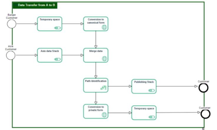
A Software Communication Chain Diagram describes the mechanism by which a content is transfered from a sender system to a receiver system. This description includes the routing, the channeling and the messages translation.
A software communication chain diagram includes:
• A Communication Start Event and a Communication End Event that designate the starting and the ending points of the described integration process.
• The Communication Sequences to describe the steps sequence.
The Communication Service types are:
• Message Channel that designate the place where an application can read or write informations.
A channel is used to identify the enterprise resources used by a persona to achieve a step. For example, a channel can be a phone or internet connexion.
• Message Router to identify the destination channel to use for the next transport step.
A message router is a communication step that identifies which route should be used for next message step.
• Message Translator to translate a message from a format to another
A message translator is a communication step that translates a message from a format to another. It can be used for trans-codification, data type conversion.
Creating a software communication chain from a scenario of flow
You can create new communication chains from flows or application flows owned by a scenario of flows.
To create a software communication chain from a flow:
1. Open the flow scenario diagram that contains the flow that interests you.
2. Select the flow that interests you to open its Diagrams properties.
3. Click Create a diagram.
The diagram creation dialog box appears.
4. Select Software Communication Chain Diagram.
The software communication chain is created as well as its diagram.
5. You can modify the Name of the software communication chain from its diagram.

Several software communication chains can be connected to the same flow.
Describing implementation of a communication service
A communication service can be processed by an application, a microservice or an application service.
To specify the software that implements a communication service; a router, for example:
1. Open the Characteristic property page the Router you are interested in.
2. Expand the Implemented Software section.
3. Click Connect.
4. In the search window, select the software that represents the execution of the service associated with the router.
5. Click OK.
The software appears in the list.