Using communication systems
A communication system is used to describe an integration process using Enterprise Integration Pattern standard (http://www.enterpriseintegrationpatterns.com).
This representation allows the modeling of application flows integration process represented in scenario of flows in HOPEX.
This report provides the distribution of multi-software communication chains.
Accessing the list of communication systems
To access the list of communication systems from the Inventories navigation menu:
The list of communication systems appears.
Communication System Properties
The complete description of a communication system is accessed in its property pages.
The Characteristics properties page for a communicate system provides access to:
• its Name,
• Its Owner, by default the application specified when it was created.
• the text of its description.
• the Software Communication Chain section which provides access to the list of components of the described communication system.
• the Communication Service section which provides access to the list of objects of the software communication chain.
Three services types can be proposed:
• Message Channel,
• Message Router,
• Message Translater,
Creating a Software Communication Chain diagram
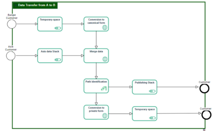
A software communication chain diagram includes:
• A Communication Start Event and a Communication End Event that designate the starting and the ending points of the described integration process.
• The Communication Sequences to describe the steps sequence. Message Channel that designate the place where an application can read or write informations.
• Message Router to identify the destination channel to use for the next transport step.
• Message Translater to translate a message from a format to another
Creating a software communication chain from the Deployment navigation menu
To create a software communication chain from the Inventories navigation menu:
1. SelectSoftware > Communication systems.
The tree of communication systems appears.
2. Right-click the communication system that interests you and select New > Software Communication Chain.
3. In the creation dialog box, enter the Name of the software communication chain and select the Tranferred Content.
4. Click OK.
The software application chain appears in the list.
Creating a software communication chain diagram from the Deployment navigation menu
To create a software communication chain diagram from the Inventories navigation menu:
1. SelectSoftware > Communication systems.
The tree of communication systems appears.
2. Expand the Software Communication Chain folder.
3. Select the software application chain that interests you and click Create Diagram.
4. In the diagram type selection window, select Software Communication Chain diagram.
5. Click OK.
The diagram opens in the edit area.
Connecting a software communication chain from a scenario of flow
You can connect a new software communication chain to a content using a scenario of flow.
To connect a software communication chain from a scenario of flow:
1. Open the flow scenario diagram that contains the content that interests you.
2. Open Integration property page of the content that interests you.
3. Click New.
The creation window for the software application chain opens.
4. Specify the Name for the new software application chain.
5. In the Owner field, select the communication system to which the new software application chain belongs.
6. Click OK.
The diagram opens in the edit area.