Using a Scenario of Application Flows Diagram
The scenario of flows diagram describes the flows exchanged between the system elements represented.
Two types of diagrams are proposed:
• The Scenario of flows diagrams that describe the flows exchanged in different use scenarios of the object described.
• Scenario of sequence diagrams that describe the chronology of the flows exchanged in different use scenarios of the object described.
A Scenario of Application Flows Diagram can be built for an application environment, an application, an application system, an IT service or a microservice. This diagram is used to describe the exchanges inside the described object in a specific context.
The scenario of application flow diagram below describes the "Purchase request management" application.
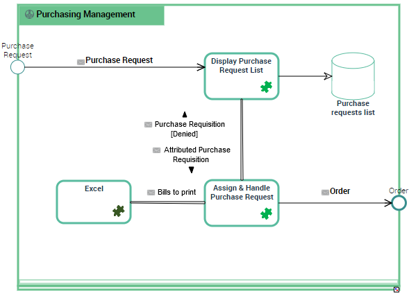
Example of a Scenario of Application Flows for "Managing Purchase Orders".
In a scenario of application flows diagram, the elements represented are:
• IT Services,services, see Describing an IT Service with HOPEX IT Architecture,
• Microservices, see Describing a microservice with HOPEX IT Architecture,
• internal or external local application data stores, see Using Data Stores,
The interactions offered between these elements:
• application flows that carry a content,
• application flow channels that group a number of application flows on a single link,
• application data channels that represent the interactions between the application data stores.
Creating a Scenario of Application Flows diagram
To create a scenario of application flows from the Applications navigation menu:
1. Right-click the application that interests you and click Create Diagram.
2. In the Create a diagram window, select Structured diagram > Internal Architecture.
The Scenario of Application Flows Diagram appears.
Adding an IT service to the scenario of application flows
To add an IT service:
1. In the objects toolbar of the scenario of application flows, click IT Service.
2. Click in the described application frame.
An addition window box prompts you to choose the IT Service implemented (for example "Customer management").
3. Select the IT Service required and click OK.
The IT Service appears in the diagram.
You can add a micoservice in the same way.
Creating an application flow with content
The application flows exchanged between IT services, microservices, or application ports in a scenario of application flows are associated with a flow and a content.
You must directly specify the content of an application flow directly on flow creation.
To create the application flow:
1. In the objects toolbar of the scenario of application flows, click Application flow and select the Type of application flow that interests you.
• Result/Provision associated to a service result,
• Call/Request associated to a service request,
• Signal associated to an information exchange.
2. Click the first object representing the sender of the flow and, holding the mouse button pressed, draw a link to the object receiving the flow.
The Application Flow Creation dialog box opens.
3. Select the communication system that will be associated to the flow.
4. In the Content drop-down list, select the content you wish to associate with the flow.
The application flow is displayed with its content in the diagram. If it doesn't exist yet, a flow is created.
Accessing a flow properties
You can access a flow properties from the application flow that references it.
To access a flow from a scenario of application flows diagram:
1. Select the application flow that interests you:
The application flow properties open to the right of the diagram.
2. In the Characteristics properties, select the flow displayed in the Flow field and open its porperties.
3. Note that the flow is characterized by a Flow Code.
Creating an application flow channel
To create an application flow channel, you must first create the channel and then link the application flows that it groups.
To create an application flow channel:
1. In the objects toolbar of the scenario of application flows, click Application Flow Channel.
2. Click the first object in communication and, holding the mouse button pressed, draw a link to the other object.
The application flow channel appears in the diagram.
To connect the application flows to the application flow channel:
1. Open the Characteristicsproperties page of the application flow channel.
2. In the Grouped Flow section, click Connect.
A selection dialog box opens and presents the list of the application flows of the scenario of application system flows.
3. Select the flows that you want to group and click OK.
The content of the selected flows is displayed in the Grouped Flow list.
4. Click the Refresh Channels button.
The application flows grouped in the channel disappears and the corresponding content is displayed around the channel.
Creating a System Triggering Event
The creation process for a Creating a System Triggering Event and a Creating a System Triggered Event is the same.
To create a System Triggering Event:
1. In the diagram insert toolbar, click the System Triggering Event button.
2. Position the object at the edge of the frame of the described object.
A creation dialog box opens.
3. Click the arrow at the right of the Referenced Content field and select the content that interests you.
4. Click Add.
The System Triggering Event appears in the diagram.
Any application flow whose origin is the System Triggering Event is connected to the same content.
To create an application flow from a System Triggering Event:
1. In the diagram insert toolbar, click Event Participation.
2. Click the event and, holding the mouse button pressed, draw a link to the object receiving the flow.
The application flow is displayed with its content associated to the event.
Reinitializing components in a scenario of flows
If you insert in a scenario of flows diagram a component that is already described by a scenario of flows, you can note that a new section is created in the Characteristics property page of the component you have added. This section allows you to specify which scenario of flows of the component corresponds to the context of the current application system scenario of flow.
In the component scenario of flows diagram, the Reinitialize components button allows you to insert components coming from the upper level scenario of flow.
Adding an application data store to the scenario of application system flows
A data store can be local or external to the application.
To add, for example, a local application data store to an scenario of application flows
1. In the scenario objects toolbar, click Local Application Data Store.
2. Click in the described application frame.
An addition window prompts you to choose the Object Type that represents the physical structure that will concretely support the application data store.
3. Depending on the Object type, select then the object that interests you.
4. Click OK.
The local application data store appears in the diagram with the name of the physical data domain selected.
Creating an application data channel
The applications, the application systems and the microservices can have read or write access to a local or external application data store.
To create an application data channel that represents a reading access:
1. In the diagram objects toolbar, click Application Data Channel.
2. Draw a link between the application data store and the object that reads the data.
An application data channel appears in the Diagram.