Relational Diagram
The Relational Diagram (RD) describes a database: it represents the physical data structures used by application programs.
Description in HOPEX Information Architecture of relational diagrams makes it possible to interface with the selected DBMS, guaranteeing semantic consistency between design data and production data.
Creating the Relational Diagram
The relational diagram is generally built in two phases:
1. Automated synchronization of the data diagram or diagrams produces the “raw“ diagram.
2. Optimizing the diagram, or denormalization, to take into account the data access requirements of the application and to fine-tune the database performance.
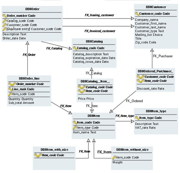
The key concept in a relational diagram is the table, which is derived from an entity or association.
A table is accessible by one or several keys, whose type indicates whether they are primary or foreign keys. It is possible to define indexes for a table, specifying their sort order (ascending or descending) and whether they are unique. Keys and indexes are connected to the columns that they contain.
Creating objects in the diagram
To create a key or an index in the relational diagram:
1. Click the table concerned.
The list of commands associated with the table appears.
2. Click Key  or Index
or IndexYou can also use the Components page in the properties dialog box of the database to create these objects. See Creating a Key and Creating an Index.
To create a foreign key:
1. Select the Key button, click the first table, and then hold the button down while dragging the mouse to the second table.
button, click the first table, and then hold the button down while dragging the mouse to the second table. The creation dialog box opens.
2. Specify the name of the key and click Add.
A second window asks you if you want to automatically create the columns of the foreign key from those of the primary key.
3. Click Yes to validate or No to create.
Configuring display of relational diagrams
As for data diagrams, you can specify which elements are to appear in the diagram:
• Either by using the Views and Details button to indicate globally the types of objects to be displayed in the diagram.
• Or by using display options that enable definition of which object characteristics should be presented.
To configure the display for a selected object: