Logical and application data areas
Logical and application data areas are used to define a logical data structure made up of classes and class views.
• The logical data area is used to describe data stores (internal or external) of logical application systems.
• The application data area is used to describe the data stores of software (Application system, Application, Application service or Micro Service).
Both are owned by a package and can reference objects held in other packages.
You can define the access mode (CRUD) to the objects referenced by a data area by integrating them as components of the data area.
Creating a logical data area
To create a logical data area:
1. Click on the navigation menu, then on Logical Data.
2. In the edit area, click Logical Data Areas.
The list of logical data areas appears.
3. Click the New button.
The creation dialog box opens.
4. Enter the name of the data area.
5. If appropriate, enter the package owner.
6. Click OK.
The data area appears in the list.
The Data Area Diagram
Logical and application data areas can be described by a diagram.
A data area diagram is a structure diagram which defines classes and their relationships in a Whole/Part formalism in connection with the subject of the data area described.
You can connect one or more data area diagrams to a data area, according to what you want to describe.
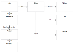
Example of diagram
The following data area diagram represents a data structure relating to Orders; it describes classes and their relationships in a Whole/Part formalism.
Creating a Logical Data Area Diagram
To create a data area diagram from a logical data area:
Adding an object to the diagram
In the data area diagram, you can add a new object or connect an existing object.
The objects visible in a data diagram are not automatically linked to the data area. A command allows you to define the objects as components of the area. See Adding a component to a data area.
Adding a class
To add a new class to a diagram:
1. In the diagram insert toolbar, click Class, then click in the diagram.
The Add A Class dialog box appears.
2. Enter the name of the class and click Add.
Add a data view
To add a new data view to a diagram:
1. In the diagram insert toolbar, click Data View, then click in the diagram.
The Add Data View dialog box appears.
2. Enter the name of the data view and click Add.
3. The editor view appears. It is used to define the components of the view. See Creating a logical data view.
Adding a component to a data area
You can connect objects to a data area through components. A component references an object (class or class view) and defines the type of access to the object in question (read-only, modification, deletion, etc.).
The data area is attached to the package; objects directly created from components are automatically connected to the package of the data area.
You can create a component from an object in the diagram or using the properties of the data area.
To create a component from an object of the data area diagram:
The name of the component created appears in the properties of the data area. By default it has the name of the object that it references.
Defining the access mode to the referenced object
On the component, you can define the access mode to the object referenced (creation, read-only, deletion, etc.).
To define the access mode to the object in the data area:
1. Open the properties of the data area.
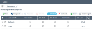
2. Click the drop-down list then Components.
The list of components of the data area appears.
3. Select the component and select the check boxes that correspond to the types of access in question (Creation, Read-only, etc.).
The Logical Data Map
A logical data map is an urbanization tool for logical information. It represents a set of data areas in a particular context.
To create a logical data map:
1. Click on the navigation menu, then on Logical Data.
2. In the navigation pane, click Logical Data Map.
3. Display all the logical data maps.
4. Click New.
The map created appears.
To create a logical data map diagram:
1. Right-click on the map and select New > Data Map Diagram.
The diagram appears in the edit area.
The components of a logical data map
You can add internal and external components in a logical data map.
The internal components are data areas that are part of the map scope (whether they belong to the owner package or not).
The external components are those used in the map but that are not part of the scope analyzed.