Composite Structure Diagram
The composite structure diagram enables description of the internal structure of a component, a package or a structured class.
It also enables specification of collaborations that intervene between elements of the structure in execution of a task, highlighting the role played by each element in the collaborations.
Elements of this diagram are parts, ports by which parts interact with the exterior, and connectors linking the parts between themselves and with the ports.
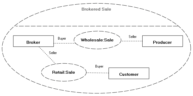
Example of a composite structure diagram
This diagram describes the role played by parts in the "Brokered Sale" collaboration.
Creating a Composite Structure Diagram
To create a composite structure diagram with HOPEX IT Architecture from Design (UML) navigation menu:
1. From the navigation sub-menu, click Components.
2. Select component stream that interests you and click New Diagram.
3. Select Composite structure diagram.
The diagram opens in the edit window.
Parts
A part represents a role played by an instance of a class or component at execution of a task.
Parts are interconnected by connectors or dependencies.
A part can also be connected, via a connector, to a port which acts as interface between the described component and the exterior.
For more details on these elements, see:
Multiplicities defined on parts indicate the number of instances created. Multiplicities on connector roles indicate the number of links that can be created for each of these instances.
To define multiplicity of a part:
1. Open the properties dialog box of the part.
2. Select the Characteristics page.
3. Click the arrow in the Multiplicity box and select the required multiplicity.
4. Click OK.
Collaborations
In the composite structure diagram, a collaboration describes the role played by each part (instance) in execution of a task.
It is represented by a dotted line oval containing the collaboration instances.
These instances are interconnected by connectors. The role that corresponds to the instance name is displayed at each end of the connector.
The model of a collaboration can be applied to different instances.
Collaboration use
A collaboration use represents application of the structure described by a collaboration to a particular situation implementing classes or specific instances. These classes or instances therefore play roles defined in the collaboration.
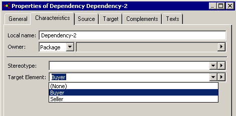
The instances are connected to the collaboration use by a dependency link on which the role played by the instance must be specified.
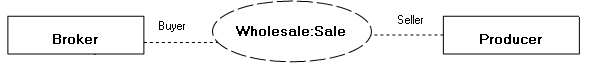
Collaboration use example
In the case of a purchasing request between two instances of an actor, a collaboration is used. This collaboration connects two roles: the role of buyer and the role of seller. On the dependency that connects each instance to the collaboration, you can indicate the role played by the instance.
Dependency links
A dependency specifies that implementation or operation of one or several elements requires the presence of one or several other elements.
A dependency is a supplier/customer type relationship indicating source and target elements in the collaboration.
A stereotype on the dependency enables specification of dependency type:
• Binding: relationship between a template and a modeling element generated from the template. It includes a list of arguments corresponding with template parameters.
• Derive : indicates a derivation relationship between modeling elements that are generally, but not necessarily, of the same type. Such a dependency relationship implies that one of the elements can be calculated from the other.
• Mapping UML/XML : expression that defines the relationship between elements (classes, attributes, ...) of a schema or class diagram and those of another schema or class diagram.
• Refine: specifies a dependency relationship between modeling elements at different semantic levels, such as analysis and design.
• Trace: specifies a traceability relationship between modeling elements or sets of modeling elements that represent the same concept in different models.
To specify dependency type:
1. Open the properties dialog box of the dependency.
2. Select the Characteristics page.
3. In the Stereotype box drop-down list, select one of the proposed stereotypes.
The arrow  also allows you to create new stereotypes.
also allows you to create new stereotypes.