Describing an Application System
A project for describing the functional architecture of an information system is also used to inventory the existing application systems and their interactions.
An application system is described by several types of diagrams:
• An application structure diagram is used to represent the service interactions between the application components using service interfaces.
• An Application System Deployment Architecture. used to represent the technical architecture chosen for the deployment of each component that support the application system as well as the techniques used for their communications .
• A scenario of application system flows presents the flows exchanged between the application systems, the applications or the microservices used by this application system. A scenario can represent a particular use case of the application system or more globally all the flows exchanged within this application system.
• Flow scenario sequence presents the agents necessary for the scenario (IT services, microservices, data stores) and exchanged sequenced application flows.
Creating an Application System
To create an application system:
1. Click Application Systems navigation menu.
The list of application systems appears.
2. Click New.
The Creation of Application System dialog box appears.
3. Enter the Name of your application system and click OK.
The new application system appears in the list.
Application System Properties
The Characteristics property page for an application system provides access to several sections.
• The Identification section provides access to the following information:
• the Name,
• its Owner, by default during creation of the application system, the current library.
• the text of its Description.
• the internal Code,
• the Version number,
• Description.
• About the Functional Scope section of the application system, see Defining Application Functional Scope.
• The Responsibility section relates to the person(s) responsible for the application system.
• Software Designer
• Local Application Owner
• The Attachments section is limited to associated attachments.
With HOPEX IT Architecture an application system is described by other property pages. See HOPEX IT Architecture properties pages content.
Creating an application system structure diagram
This diagram describes the internal structure of an application system:
• services offered or required,
• the application components and their interactions; these are application systems service, applications and microservices,
• the end users interacting with the application components.
The following diagram describes the application system corresponding to purchasing requests processing.
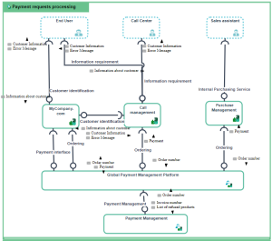
The following diagram describes the application system corresponding to purchasing requests processing.
To create an application system structure diagram:
1. Open the Diagram page of the application system of your choice and click Create a diagram.
2. Select Structured diagram > Internal Architecture.
The application system structure diagram appears.
Adding an application system to an application system structure diagram
To describe an application system that implements another application system, you can add an application system of the application system structure diagram.
For example, the purchasing requests processing system uses the "Purchasing Management Platform" and "Payment Management" application system services.
To add an Application System:
1. In the objects toolbar of the application system structure diagram, click  Application System.
Application System.2. Click in the frame of the described application system.
An addition window box prompts you to choose the application system implemented (for example "Payment management").
3. Select an application system.
4. Click OK.
The application system appears in the diagram.
Adding an end user to an application system structure diagram
To specify that an application system, such as purchasing request processing, is activated by internal or external org-units, you will add an associated end user.
To add an end user:
1. In the application system structure diagram objects toolbar, click  End User and click in the frame of the diagram.
End User and click in the frame of the diagram.An addition window prompts you to choose the Object Type that you wish to use: Org-Unit or Position type.
2. For example, select the Org-unit object type.
3. Select the org-unit that interests you and click OK.
The actor appears in the diagram.
Using a Scenario of Application System Flows
A scenario of application system flows represents the flows exchanged between certain elements of the application system in a given context. The elements represented are:
• application systems,
• applications,
• micro services,
• organization org-units,
• internal or external local application data stores,
• input or output application ports.
The interactions offered between these elements:
• application flows that carry a content,
• application flow channels that group a number of application flows on a single link,
• application data channels that represent the interactions between the application data stores.
The scenario of application system flows below describes the interactions between a client and the eCommerce application.
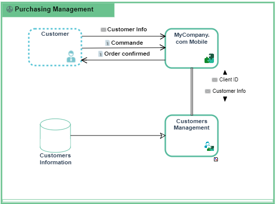
Example of scenario of application system flows for "Purchasing Requests Processing".
To create a scenario of application system flows diagram:
1. Open the Diagrams page of the application system of your choice and click Create a diagram.
2. Select Structured Diagram > External Data Flows.
The Scenario of application system flows diagram appears.
Adding an org-unit to the Scenario of Application System Flows
An org-unit is represented by an Org-Unit or by a Position type.
To add an organization unit:
1. In the scenario of application system flows object toolbar, Org Unit.
2. Click in the frame of the described application system.
An addition window prompts you to choose the org-unit name you wish to use:
3. Select the org-unit that interests you and click OK.
The actor appears in the diagram.
Adding a scenario of application system flows
To add an application:
1. In the scenario of application system flows object toolbar, click Application.
2. Click in the frame of the described application system.
An addition dialog box prompts you to choose the application that you want to use (for example "eCommerce purchase").
3. Select the application and click OK.
The application appears in the diagram.
In the same way you can add:
• an application system
• a microservice.
If the component we have added in the scenario of application system flows is already described by a scenario of flows, a new section is created in the Characteristics property page of the component.
For further details, see .For further details, see Reinitializing components in a scenario of flows.