NOV-2 Operational Node Connectivity Description
NOV-2 graphically depicts the operational nodes (or organizations) with needlines between the nodes that indicate a need to exchange information.
The graphic includes:
• internal operational nodes (internal to the architecture)
• external nodes.
NOV-2 is intended to track the need to exchange information from specific operational nodes (that play a key role in the architecture) to others. It does not depict the connectivity between nodes.
Using Operational Nodes
To create an operational node:
1. In the NAF navigation tree, click Operational Views > NOV-2.
The operational nodes available for the operational view appear in the Root Operational Nodes folder.
2. Right-click the Root Operational Node folder and select Operational node.
3. In the dialog box that appears enter the name of the operational node.
4. Click OK.
The new operational node appears.
Creating Operational Node Structure Diagrams
After creating your operational nodes the need for information exchange between operational nodes can be illustrated in the Operational Node Structure Diagram. This information exchange is represented by interactions created between the nodes. The diagram shows how operational nodes and interactions interact with each other.
An Operational Node Structure Diagram details the structure of an operational node. The node is composed of sub-nodes that are connected to each other through interactions.
Below is an example of an operational node structure diagram. The operational nodes are represented by yellow rectangles.
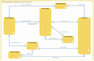
Example of an Operational Node Structure Diagram (no content displayed)
The described node establishes a context for the interactions. For this reason sub-nodes are not directly connected in the diagram.
As sub-nodes can be reused in other contexts the interactions link the intermediate objects that reference the sub-nodes and that are defined locally within the context of the node. This way you can differentiate the interactions performed in one node context from those performed in another node context. In the case of operational nodes, the intermediate objects are called Operational Components. If no name is set for an operational component, a name is automatically created from the referenced operational node.
To create an operational node structure diagram:
1. In the NAF navigation tree click Operational Views > NOV-2.
2. Right-click the operational node concerned and select New > Operational Node Structure Diagram.
The new diagram opens with a Root Operational Node positioned in it.
Adding operational nodes to the diagram
Operational nodes in the Structure diagram are referred to as operational components.
To add an operational component to the diagram:
1. Click the Operational Component icon  in the object bar and click in the diagram.
in the object bar and click in the diagram.2. In the Add Operational node dialog box that appears, select the operational node concerned from the drop-down list.
3. Repeat this step to create as many operational nodes as necessary.
Adding interactions to operational nodes
After creating your operational nodes you can display the interactions between them. Interactions describe the information that can be exchanged between two nodes.
To add an interaction to operational nodes:
1. In the objects toolbar for a diagram, click Interaction 
2. Click the entity requesting the service and draw a link to the entity providing the service.
3. In the add interaction dialog box, specify the exchange contract you wish to use.
4. Click Add.
Adding content to interactions
It is possible to add and display the content of interactions in the different structure diagrams.
Content of an interaction is described by an exchange contract.
In a service-oriented architecture, communication is based on service points and request points.
For more details, see Adding Service and Request Points to Operational Nodes.
Adding Service and Request Points to Operational Nodes
Interaction with an operational node can be made through interaction points. Interaction points are ports for information exchanges. When a node is used as a sub-node in an operational structure, it can interact with another node through these interaction points.
In relation to the information in his possession, the designer of the structure can describe the interactions between two sub-nodes and specify the points of these sub-nodes that the interaction uses to exchange the information.
There are two kinds of interaction points:
• service point
• request point.
Service points
The service point is used to interact with the node that is considered to be the provider of the information exchanged. In this case, the interacting item at the other end of the interaction is the requester of the information that the node is able to supply.
Request points
Request points on the other hand are used for interacting with the node that is considered to be the consumer in the interaction.
Creating Realization of Operational Nodes
An operational node may implement a capability. To describe the capabilities implemented, you must define a Realization on the operation node in question.
To describe that a operational node is implementing a capability:
1. In the NAF navigation tree, click Operational Views > NOV-2.
2. Open the property page of the operational node that interests you.
3. Select the Characteristics > Realizations page.
4. In the Composite Realization section, click New.
The selection window opens.
5. Select "Business Capability fulfillment” and click OK.
6. Chose the capability implemented.
7. Click Add.
The capability realization appears in the properties page.