Describing a Logical Application System with HOPEX IT Architecture
A project for describing the logical architecture of an information system inventories the existing logical application systems and their interactions.
A Logical Application System can be described by two types of diagram.
• an application system structure diagram that represents the different components of the application system and their interactions.
• A scenario of logical application system flow diagram is used to describe the exchanges inside the described logical application system in a specific context.
Accessing the list of logical application systems with HOPEX IT Architecture
To access the list of logical application systems form Inventories navigation menu:
The tree of logical application systems appears.
Creating a Logical Application System
To create a logical application system:
1. From the Inventories navigation menu, select Software > Logical Software Architecture.
2. Click the New button.
The Creation of a Logical Application System dialog box appears.
3. Enter the Name of your logical application system as well as its Owner and click OK.
The new logical application system appears in the list.
Logical Application System Properties
The Characteristics properties page for a logical application system provides access to:
• its Name,
• its Owner, by default, during creation of the logical application system, the current library.
• the text of its Description.
With HOPEX IT Architecture, a logical application system is described by the following pages:
• the Properties page, used to specify the properties that appear in the diagrams at the bottom of the described object frame.
• the Component page provides access to the list of application system components described in its different diagrams as well as the communications that exist between them.
• the Implementation page is used to specify the logical or physical elements that implement the described logical application system.
Describing a logical application system structure
With HOPEX IT Architecture, the components of a logical application system and their exchanges are described in a logical application system structure diagram.
The logical application system structure diagram, for managing "Internet Purchase Requests", presents different logical applications, access to a logical database as well as service and request points for "Book" or "Order".
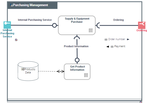
“ Purchasing request Management” Logical application system structure diagram
A logical application system structure diagram includes the following elements:
• end users
• Logical Application System Components and Logical Application Components
• Service interactions between the components representing requests for services
• service points
• request points
Adding an end user to the logical application system structure diagram
To create an end user:
1. In the objects toolbar of the logical application system structure diagram, click End User.
2. Click in the frame of the described logical application system.
An addition window prompts you to choose the Object Type that you wish to use:
3. For example, select the Org-unit object type.
4. Select the org-unit that interests you and click OK.
The actor appears in the diagram.
Adding a logical application to a logical application system structure diagram
To describe that a logical application system implements a logical application:
1. In the objects toolbar of the logical application system structure diagram, click Logical Application component and click in the frame of the logical application system described.
An addition dialog box prompts you to select the Logical Application used.
2. Select an existing logical application.
3. Click OK.
The logical application appears in the diagram.