Using IT architecture diagrams
With HOPEX IT Architecture, the internal architecture of an application object is described by a structure diagram representing the object components their exchanges. A Structure diagram can be designed for an application, an application environment, an application system, an application system environement, a logical application system, an application service or a microservice.
The Internal Data Flows of an application object are represented in a scenario of flow diagram describing the messages exchanged between the object components. With HOPEX IT Architecture, you can design two types of scenario diagrams:
• The Scenario of flows diagrams that describe the flows exchanged in different use scenarios of the object described.
• Scenario of sequence diagrams that describe the chronology of the flows exchanged in different use scenarios of the object described.
Creating a structure diagram
To create a, Application system structure diagram, for example:
1. Open the Diagrams property page of the application system and click Create a diagram.
2. In the choice window, select Structured diagram > Internal Architecture.
The diagram opens in the edit area. You are now in the HOPEX graphic editor. The frame of the described object appears in the diagram.
Example of an application system structure diagram
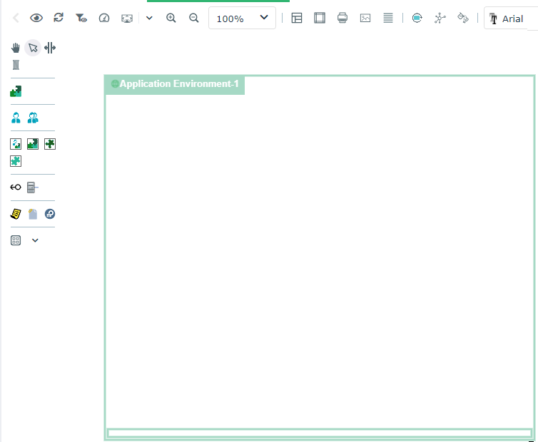
By default, the diagram is initialized with the described object, represented by a frame; the components of the described object are positioned at the top of the diagram.
If the described object is represented in a higher level diagram, the new diagram is initialized taking into account participants and flows that are represented in the higher level diagram.
Diagram commands with HOPEX IT Architecture
Depending on their type, HOPEX IT Architecture diagrams propose specific commands.
Icon | Description |
|---|---|
 | Refresh channels Allows to update the content of the channels described in a scenario of flows. See Creating an application flow channel. |
 | Reinitialize components Add, in the diagram, the components of the first level of the described object. |
 | Auto Layout Enables to organize automatically the described object components in the diagram. See Auto Layout in architecture diagrams. |
 | Add Items Enables to complete the current diagram with the elements defined in other diagrams. See Environment diagram initialization. Available only for application environment and application system environment diagrams. |
Auto Layout in architecture diagrams
If the environment contains components and interactions between components, each new diagram is initialized with these components displayed at the top left of the frame of the described environment.
The Auto Layout button allows you to reorganize the diagram elements taking into account the exchanged flows.
The Diagram compression/dilatation coefficient enables the specification of the distance to be expected between elements.
When you use the Auto Layout function, the previous presentation of your diagram is lost.
The auto layout facility is proposed for the following diagrams:
• Application Environment
• Application Environment Diagram
• Scenario of Application Environment Flows Diagram
• Application
• Scenario of Application Flows Diagram
• Application Structure Diagram
• Application Deployment Environment Diagram
• Application System Environment
• Scenario of Application System Environment Flows
• Application System Environment Diagram
• Application System
• Scenario of Application System Flows
• Application System Structure Diagram
• IT Service
• Scenario of IT Service Flow Diagram
• IT Service Structure Diagram
• Logical Application
• Scenario of Logical Application Flows Diagram
• Logical application structure diagramme
• Logical Application Deployment Environment Diagram
• Logical Application System Environment
• Logical Application System Environment Diagram
• Scenario of Application System Environment
• Logical application system
• Structure diagram of the logical application system
• Scenario of Logical Application System
• Resource Architecture Environment
• Resource Architecture Environment Diagram
Environment diagram initialization
An environment diagram represents a use context of an application or an application system.
In order to simplify the description of a specific use context of an application system, for example, Add Items button provides the list of components with which the application system interacts and helps you to select the objects you wish to add in your diagram.
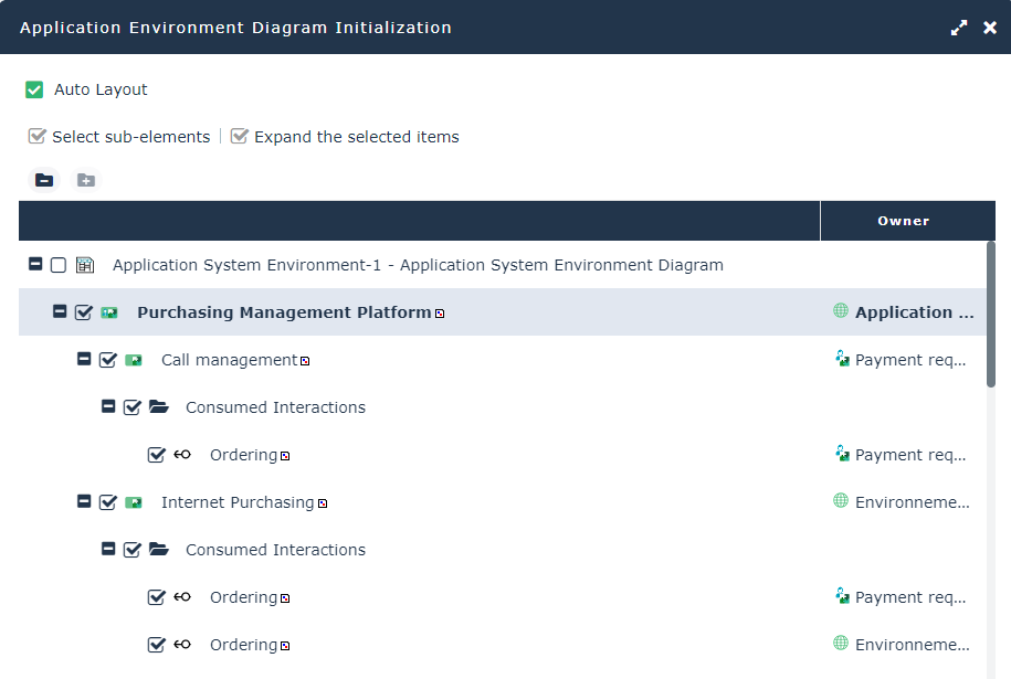
The Sub-Elements selection and Expand selected elements buttons help you in your selection.
Creating a Sketching diagram with HOPEX IT Architecture
A sketching diagram is a drawing that enables you to exchange with your coworkers without an issue of methodology or formalism.
Sketching diagrams can then be reworked and transformed into diagrams recognized by a HOPEX Solution.
To create a sketching diagram for an application, for example, with HOPEX IT Architecture:
1. From the Applications navigation menu, select the application of interest to you and click Create a diagram.
2. In the wizard window, select Sketching diagram.
The diagram opens in the edit area. You are now in the HOPEX graphic editor.
Creating an ArchiMate@ diagram with HOPEX IT Architecture
HOPEX for the ArchiMate® Framework product provides facilities to use the set of concepts defined by the Open Group for ArchiMate®. ArchiMate® concepts are mapped with HOPEX Enterprise Architecture building blocks so as to manage compatibility and continuity with other models.
You can associate a diagram based on ArchiMate@ formalism to an application, for example.
Using diagram comparison
The comparison of diagrams of an application system or architecture of an application system deployment enables to compare different versions of the same object.