Using IT architecture diagrams
With HOPEX IT Architecture, the components of an application object and their exchanges are described in a structure diagram. A structure diagram can be built for an application, an application environment, an application system, an application system environment, a logical application, a logical application system, an IT service or a micro-service.
The scenario of flows diagram describes the flows exchanged between the system elements represented. With HOPEX IT Architecture, two types of diagrams are proposed:
• The Scenario of flows diagrams that describe the flows exchanged in different use scenarios of the object described.
• Scenario of sequence diagrams that describe the chronology of the flows exchanged in different use scenarios of the object described.
Creating a structure diagram
To create an Application Environment Structure Diagram, for example:
1. Select the application environment that interests you and click Create Diagram button.
2. In the dialog box, select Application Environment.
The diagram opens in the edit area. You are now in the HOPEX graphic editor. The frame of the described object appears in the diagram.
Example
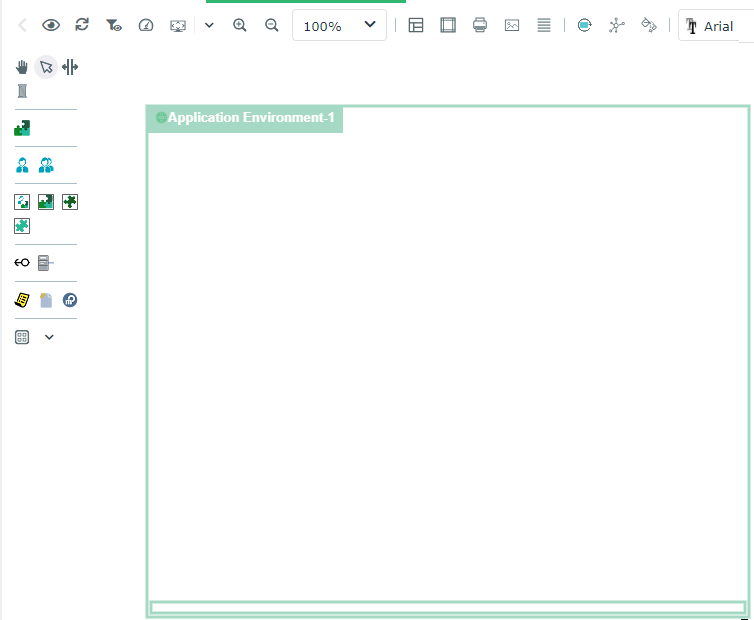
By default, the diagram is initialized with the described object, represented by a frame; the components of the described object are positioned at the top of the diagram.
If the described object is represented in a higher level diagram, the new diagram is initialized taking into account participants and flows that are represented in the higher level diagram.
Diagram commands with HOPEX IT Architecture
Depending on their type, HOPEX IT Architecture diagrams propose specific commands.
Icon | Description |
|---|---|
 | Refresh diagram Refreshes the diagram, for example if some components have been removed from the repository. |
 | Diagram properties Provides access to the diagram properties |
 | Refresh channels Allows to update the content of the channels described in a scenario of flows. See Creating an application flow channel. |
 | Reinitialize components Add, in the diagram, the components of the first level of the described object. |
 | Auto Layout Enables to organize automatically the described object components in the diagram. See Auto Layout in architecture diagrams. |
 | Initialization Enables to add a selection of components in the diagram. See Environment diagram initialization. Available only for application environment and application system environment diagrams. |
Environment diagram initialization
An environment diagram represents a use context of an application or an application system.
In order to simplify the description of a specific use context of an application system, for example, the Initialization button provides the list of components with which the application system interacts and helps you to select the objects you wish to add in your diagram.
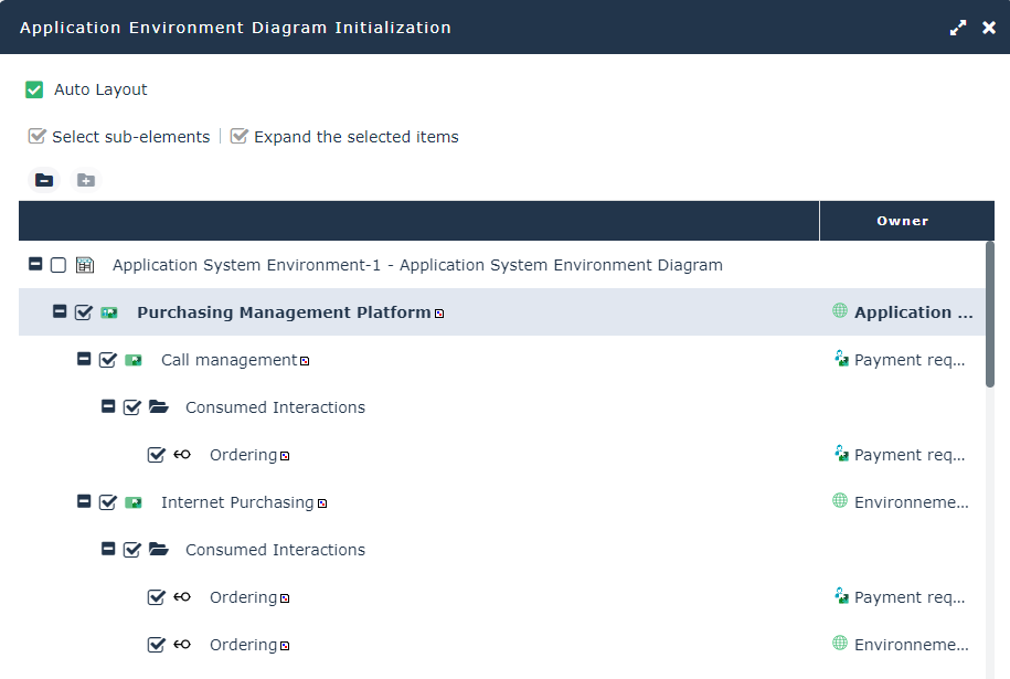
The Sub-Elements selection and Expand selected elements buttons help you in your selection.
Auto Layout in architecture diagrams
If the environment contains components and interactions between components, each new diagram is initialized with these components displayed at the top of the frame on the left of the frame of the described environment.
The Auto Layout button allows you to reorganize the diagram elements taking into account the exchanged flows.
The Diagram compression/dilatation coefficient enables the specification of the distance to be expected between elements.
When you use the Auto Layout function, the previous presentation of your diagram is lost.
The auto layout facility is proposed for the following diagrams:
• Application Environment
• Application Environment Diagram
• Scenario of Application Environment Flows Diagram
• Application
• Scenario of Application Flows Diagram
• Application Structure Diagram
• Application Deployment Environment Diagram
• Application System Environment
• Scenario of Application System Environment Flows
• Application System Environment Diagram
• Application System
• Scenario of Application System Flows
• Application System Structure Diagram
• IT Service
• Scenario of IT Service Flow Diagram
• IT Service Structure Diagram
• Logical Application
• Logical Application System Environment
• Logical Application System Environment Diagram
• Scenario of Application System Environment
• Logical application system
• Structure diagram of the logical application system
• Scenario of Logical Application System
• Resource Architecture Environment
• Resource Architecture Environment Diagram
Using diagram comparison
The comparison of diagrams describing an application system, an application or a deployment architecture enables the comparison of several versions of a same building block.