Building Concept Diagrams
A concept diagram is a graphical representation of the concepts used in the context of a business information area, as well as the links that exist between these concepts.
A business information area can be described by a number of concept diagrams.
A conceptual object belongs to a subject area from which it was created but can be used/referenced by a business information area of a different subject area.
See also Defining a Business Information Area.
Creating a concept diagram of a business information area
To create the concept diagram of a business information area:
The concept diagram opens in the Edit window.
The components of a concept diagram
A concept diagram describes the information architecture. By default, you see in the concept diagram concepts, variations and individuals only.
The following concept diagram partially describes the "Media Library" subject area.
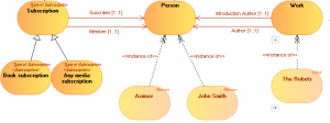
Concept graph diagram with standard views
Activating the views window
The Views and Details window presents an extended list of views (object types to be displayed).
To activate the Views and Details window:
1. In a diagram, click  Views and Details.
Views and Details.The list of views (object types to be displayed) appears.
2. Select or clear the views you wish to display or not.
The views available for a business information area are:
• Concepts,
• Concept types,
• State concepts,
• Event concepts,
• Individuals,
• Individual states,
• Individual events,
• Concept Views
Adding a concept diagram element
For example, to add an existing concept to a business information area:
1. In the concept diagram object toolbar, click  Concept.
Concept.2. Click on the diagram.
The add concept dialog box opens and asks you to select a concept.
3. Select the concept that interests you.
4. Click Add.
The concept appears in the diagram.
Using the object insert toolbar
An insert toolbar available on each object simplifies object creation by proposing object selection help. It proposes only those objects that can be connected to the current object.
To create, for example, a concept from a diagram concept:
1. Click on the concept of the diagram that interests you.
The bar containing the objects you can insert at this stage appears.
2. Click the icon that represents the object you wish to create.
For example: Concept .
.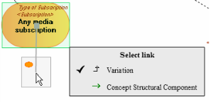
The link selection dialog box appears.
3. In the link selection dialog box, select the desired link type.
For example: Concept Structural Component.
4. Click in the graph at the point where you wish to place the object.
The object is created, with the link to the previous object.
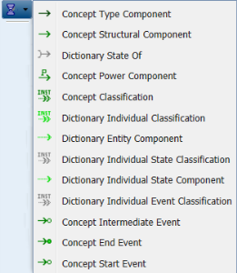
Overview of links between objects
In each concept graph, relationships between concepts, concept types and concept individuals are represented by links.
The link direction provides a natural mechanism for reading and deducing the scope defining "the business object".
Link type | Definition and Comment |
|---|---|
Concept type component | A concept type component enables specification of the relationship between two concept types. |
Concept structural component | A concept structural component enables representation of a dependency relationship between two concepts. This relationship is directional. |
Dictionary state of | A dictionary state enables connection of a concept to a concept state, and specification of the state nature. With "State concept" view. |
Concept Power Component | A concept power component enables connection of a concept to concept type to characterize a property of the concept. |
Concept classification | A concept classification enables connection of a concept to the concept that characterizes it. |
Individual classification | An individual classification is used to connect an individual to the concept that characterizes it. |
Dictionary entity component | An entity component is used to connect an individual to a dictionary element. |
Individual state classification | An individual state classification enables connection of an individual state to the state concept that characterizes it. This link is available with "Individual State" view. |
Individual state component | An individual state component is used to connect an individual to an individual state. This link is available with "Individual State" view. |
Individual event classification | An individual event classification is used to connect an individual to the event concept that characterizes it. This link is available with "Individual State" view. |
Concept intermediate event | An event concept represents an event occurring during concept life, for example a change of season. An event concept marks the impact on a concept of a phenomenon internal or external to the concept. Concept events can be distinguished as concept start events, end events and intermediate events. These links are available with "Event Concept" view. |
Concept end event | |
Concept start event |
Accessing link properties in a concept diagram
In a concept diagram, links are directional and access the properties of both the link and the link target object.
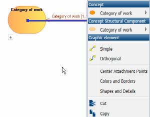
The pop-up menu of a Concept Structural Component link type for example presents:
• commands specific to the object type used by the component
for example Concept
• commands relating to the component itself
for example Concept Structural Component
• commands relating to the graphics.
To access properties of a link of "component" type:
for example Concept Structural Component
1. Right-click the link to open its pop-up menu.
2. Select the link and click Properties.
The link properties dialog box opens.
In the Characteristics tab of link properties, provides several information.
• The Local Name of the link, which corresponds by default to the target dictionary element or term associated with the link.
• The Composed Concept targeted by the link.
• The Owner who is the dictionary element at the origin of the link.
• The Minimum Multiplicity is the number of origin elements that can access the same target elements.
For example, how many "Works" can belong to the same "Work Category".
• The Maximum Multiplicity is the number of target elements that can be connected to the same origin elements.
For example, a "Work" can only belong to only one "Work Category".
• The Dictionary Abstract Type check box, which enables specification of the concrete or abstract character of a concept
• Dictionary Scope Property which can be one of the following:
• "Referencing”: to indicate that the target concept is referenced by a link,
• "Embedded": to indicate that the target concept exists in its own right, but is included in the concept that is the source of the link,
• "Composite": to indicate that the target concept is a component of the concept that is the source of the link; if the target concept is destroyed, the composite is also destroyed.
• The Designation of the link and the Definition Text field enable association of a term and a definition to the link.
• Super-types that are used to access the properties of a linked inherited from a concept type.
• The Realization, which is used to associate this dictionary element with others application architecture elements.
• Synonyms, which are used to specify a list of synonyms.
For more details on defining concepts, see Describing Concepts.