Defining Object Life
To enable detailed analysis of repository object master plans, you can describe, from an object life, the planning of steps in the object life cycle.

The life of an object is a set of time periods representing the real calendar of object states.
An object life can be defined for:
• a business process
• an application
• a hardware item.
Viewing Application Life (Gantt Chart)
An object evolving over time can take different states (preparation, production, retirement, etc.).
The Object life enables viewing of the planning of these different states in the form of a Gantt chart.
To view the Gantt chart representing the different states of an application for example:
1. Right-click the application and open its Properties window.
2. Select the Characteristics > Characteristics page then the Gantt section
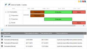
Gantt chart example
The first line shows the synthesis of the life cycle of the application (here "Billing"), with the sequence of different states. Under this line you access the details of the time periods associated with each state (preparation, production, etc.).
The object life is characterized by:
• a Life Cycle which enables definition of the list of possible states of the object.
• a Begin Date and an End Date which enable definition of the time periods over which the different states are spread.
From information on the object life, the Gantt chart represents planning of the different steps in time.
Specifying Object Life
Creating an object life
The procedure varies slightly depending on whether you are in Web Front-End or Windows Front-End.
To create the object life of an application for example:
The life of an object is a set of time periods representing the real calendar of object states.
1. Right-click the object, here the application, and open its Properties.
2. [Windows Front-End] Click the Object life tab.
[Web Front-End] Click the drop-down list then Object life.
The Object Life window appears.
3. Click the New button.
4. Specify the following characteristics:
• a Life Cycle which enables definition of the list of possible states of the object.
• a Begin Date and an End Date which enable positioning of the object life in time.
5. Click OK.
The object life appears in the Gantt chart of the application.
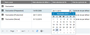
Updating the dates of the object life
By default, the different steps in the object life cycle are distributed in equal time periods between object life begin and end dates.
These dates are accessible and can be modified in the application Gantt chart.
Accessing properties of a time period
In the Gantt chart, the pop-up menu of a time period presents commands specific to the described application ("Billing" in our example), followed by the commands relating to the time period itself.
To access properties of a time period of the application life:
1. In the Gantt chart, right-click the time period.
2. In the time period pop-up menu, select Properties.
Defining Life Cycle of an Object Type
Overview of Concepts
The life cycle of an object defines the list of possible object states.
A life cycle is defined by a "State Machine".
A state machine is the set of states and transitions between states that define the life cycle of an object variable over time. A state machine can be associated with several life cycles.
A state machine is associated with object types (MetaClasses): states of this machine are therefore valid for objects of associated types.
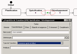
State diagram
The state diagram describes the sequence of states operating during the life cycle of an element. Each state, which can be considered as a point in time, is followed by other states.
Passage from one state to another is modeled by a transition.
Passage between states
Passage from one state to another is modeled by a transition. On this transition you can specify state sequencing:
• Starts After End: the next state can intervene when the previous state has been completed.
• Starts After Start: the next state can intervene when the previous state has started, whether or not it is completed.
Life cycles supplied by default
HOPEX provides a standard state machine for applications and artifacts.
A default state machine is provided for all artifacts; this is "Artifacts Default Life Cycle".
An artifact is any type of physical element outside the application or organizational domain (organizational including persons). An artifact can represent a hardware system, sub-system, platform or component, or simply a physical element with specific characteristics.
The life cycle described in this state machine includes three states: Preparation, Production, Retirement. It is valid for all time-dependent objects.
Creating state machines other than those defined as standard
Modifying a standard state machine has consequences on data already modeled in the repository. It is therefore a modification that should be restricted to appropriate authorization levels.
To formalize states other than those supplied as standard by HOPEX, it is preferable to create a new state machine.
To create a state machine from a library:
1. [Windows Front-End] Open the Home navigation tree.
2. [Web Front-End] Click the Repository navigation pane, then Library.
3. Right-click the library concerned and select New > Model Building Block.
A dialog box prompts you to specify the type of object to be created.
4. Select the "State machine" MetaClass.
The Creation of State Machine dialog box appears.
5. Enter its Name.
6. Click Next.
The new dialog box allows you to specify the list of MetaClasses that can be associated with the life cycle created.
7. In the Valid Type section, click Connect.
Several default queries are proposed to assist you in your choice.
8. Select for example "Types of objects that can be planned".
9. Select the MetaClasses that interest you and click OK.
The list of selected MetaClasses appears in the dialog box.
10. Click Finish.
To describe states associated to this new state machine, you must create a state diagram.

For more details on the use of state diagrams, see the guide
HOPEX UML.