Using a Flow Scenario Sequence Diagram

To use Scenario of Application Flows Diagrams, open the
Options window and check that
IT Architecture > Activate Flow Scenario Sequence Diagrams option is activated.
This type of diagram can be built for an application system, an application environment, an application, an application, an IT service or a microservice.
For each use context, you create flow scenario sequence diagrams. A flow scenario sequence diagram presents the same exchanges between system elements, highlighting their chronology. The elements in the sequence scenario are represented in the diagram by lines.
A flow scenario sequence diagram contains:
• Lines which define service interaction participants: instances of applications, services or interfaces.
• Different types of messages exchanged between participants.
• Advanced functions that enable concise description of several execution sequences.
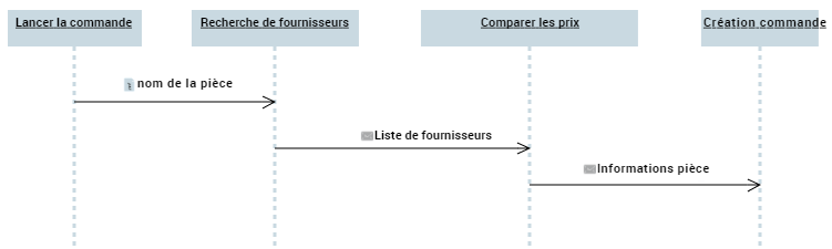
This diagram describes the operation of the "Order Unreferenced Parts" use case:
When a purchase request is entered in the user interface, the name of the part is received by the "Find Suppliers" service, which draws up the list of suppliers offering the requested part.
The "Compare Prices" service looks for the lowest-priced product and sends information to the "Order Amount Calculation" service.
When the order amount has been established, a final "Issue Purchase Order" service sends the order via the interface.
Creating a flow scenario sequence diagram
To create an application environment scenario sequence:
1. Open the Diagram page of the application environment that interests you and click New.
2. In the dialog box, select Scenario of Application Environment Flows - Application Environment Scenario Sequence Diagram.
Instances of applications, IT services or interfaces
Depending on whether the diagram describes a user interface, an application or an IT service, the service interaction scenario diagram describes messages exchanged between application instances, IT service instances and user interface instances.

A Human-Machine Interface enables definition of a screen of an application or an IT service.
An IT service is a software component of an application, that can't be deployed alone and that realizes a sub-set of the functionalities of this application either for end users of this application or inside the application (or another application). This includes batch programs.
To create an IT Service instance for example:
1. Click the IT Service button in the toolbar.
2. Click in the diagram.
The Add IT Service dialog box appears.
3. Click the arrow to the right of the Name field and select Connect IT Service in the drop-down list.
The list of IT Services accessible from the current library appears.
4. Select the IT service you require.
5. Click OK.
The IT Service instance appears in the diagram.
Message instance
Message instances define the data exchanged between application instances, IT Services and the interfaces. The sequence described in the flow scenario sequence diagram indicates the message sending order.
Message instances displayed in sequence scenario diagram correspond to messages owned by the application that have been previously defined in another diagram.
To create a message instance:
1. Click the reel in the toolbar.
2. Click the dotted line under the first object and, holding the mouse button down, draw a line to the second object.
3. Release the mouse button.
The message instance exchanged between the two objects is drawn.