Creating a Process Diagram in Graphical Mode
To create a process diagram in graphical mode:
1. In the process list, click the Create Diagram  icon related to the selected process.
icon related to the selected process.2. Select Create a diagram in graphical mode.
The diagram creation window opens.
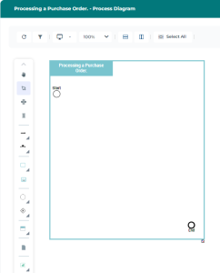
3. To complete the process diagram, add existing or new objects into the frame, using the following icons:
• Sequence Flow 
• Message Flow with Content 
• Operation 
• Processes 
• Event 
• Gateway 
• Participant 
• Data Object 
• Application Used 
• Risks  and Control
and Control Object display
Some objects are not displayed by default in the graphical editor. To make them appear:
 icon.
icon. 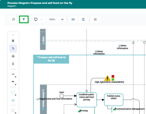
Actions on objects
For more details on:
• Adding objects, see Adding Objects to a Diagram.
• Links between, see Handling Links Between Objects.
• Deleting objects, see Removing and Deleting an Object from a Diagram.
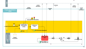
Object coloring
To highlight an object, you can change the color of its graphical shape (fill and/or outline).
Rearranging objects in the diagram
The following icons allow you to automatically rearrange the objects in the diagram:
• BPMN Vertical Diagram  : Rearranges the diagram objects vertically.
: Rearranges the diagram objects vertically.• BPMN horizontal Diagram  : Rearranges the diagram objects horizontally.
: Rearranges the diagram objects horizontally.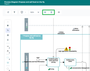
Diagram rearrangement thresholds
Rearranging a complex diagram may take several minutes.
By default, a warning appears if the diagram contains more than 50 Sequence Flows, requiring user confirmation before proceeding with the rearrangement.
To adjust this value:
By default, automatic rearrangement is disabled if the diagram contains more than 100 Sequence Flows.
To adjust this value: