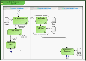
System Process Diagrams
The system process (system function) diagram uses the notation proposed by BPMN standard.
To create a system process diagram:
1. In the navigation bar, select Systems Viewpoint > SV-4 Systems Functionality Description > System Functions.
2. Right-click the system function and select System Process Diagram.
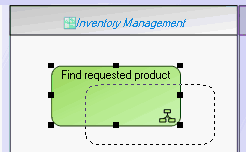
Example of system function diagram
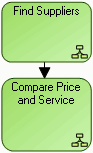
Tasks
Sequence Flows, Events and Message Flows
Sequence flows
Organization of system functions is represented by sequence flows between system functions.
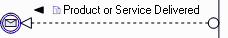
Events
Events represent facts occurring during system function execution. An example is the start  or end
  of the system function.
or end of the system function.Message flows
Message flows represent exchanges between the system function and the outside.
System Process Gateways
In compliance with the BPMN standard, in the object toolbar, several gateway types are available to you.
To better understand the main use cases, we distinguish output gateways of a processing step from input gateways.
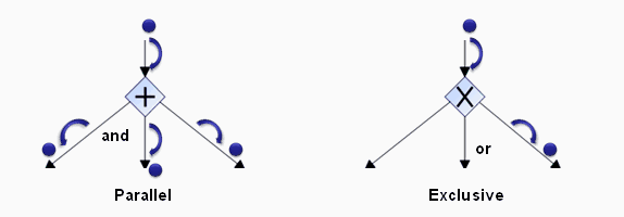
Processing Step Output Gateways
In the case of an Exclusive gateway, only one output branch can be selected from those available. The branch can be selected as a function of the Data available for the function, or of the Events occurring during its execution.
In the case of a Parallel gateway, all output branches are processed simultaneously.
In the case of a Complex gateway, one or several output branches can be selected from those available. A Complex gateway represents a combination of those above. When the gateway has been created, its type can be modified in its properties dialog box. At output of a step, a gateway represents a point of divergence of sequence flows of a system function.
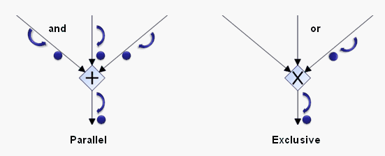
Step Input Gateways
At input of a step, a gateway represents a point of convergence of sequence flows of a system function. In the case of an Exclusive gateway, the system function step is triggered when one of these branches is active. In the case of a Parallel gateway, all input branches are processed simultaneously.
Creating gateways
To create a gateway:
1. Click the arrow at the right of the Gateway button in the diagram insert toolbar and select the gateway type you wish to create.
2. Click on the diagram.
The gateway appears in the diagram with the shape appropriate to its type.
To modify a gateway:
1. Right-click the gateway and select Properties in its pop-up menu.
The properties windows opens.
2. Click Characteristics.
You can modify the name or type of the gateway.
The different gateway types proposed are:
• Complex: the process can take a complex combination of paths.
• Exclusive (Data): the process can take a single path from several possible paths depending on the value of the data available. This is the default gateway type.
• Exclusive (Start): the process is triggered by the first event occurring; others are ignored.
• Exclusive (Event): the process can take a single path from several possible paths depending on the events occurring.
• Inclusive: the process can take one or several paths simultaneously.
• Parallel: the process takes several parallel paths simultaneously.
• Parallel (Start): the process is triggered by the first event occurring. The other events occurring during progress of the process are also taken into account.
3. Click OK.
Creating a System Process Participant
In a system process diagram, a participant enables grouping of tasks assigned to a system or service.
To create a participant:
1. In the diagram insert toolbar, click the arrow at the right of the  Participant button.
Participant button.2. In the list proposed, select for example Application Participant and click in the diagram.
The participant creation dialog box appears.
3. Click the arrow  at the right of the Application field and select Connect Application.
at the right of the Application field and select Connect Application.The query dialog box appears.
4. Find the application and click Connect.
5. In the participant creation dialog box, click OK (Web Front-End) or Finish (Windows Front-End).
The participant created appears in the diagram with a header containing the name of the assigned application.
To assign a task to a participant: