SVcV-10c System Flow Scenario Diagram
A system flow scenario represents the flows exchanged between the elements of the system in a given context.
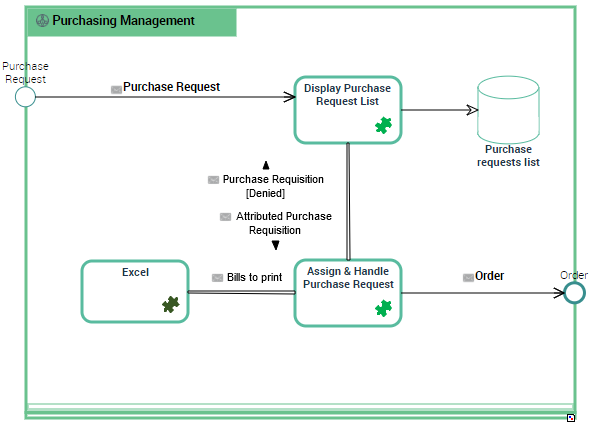
Example of "eCommerce Purchasing" system flow scenario
The Application Flow Scenario above describes the exchanges between the “Purchase request management” and the other purchase services.
Creating a system flow scenario diagram
To create a system flow scenario diagram:
1. In the navigation bar, click Systems Viewpoint > SV-10c Systems Event-Trace Description > Scenarios of System Flows.
2. Create a system flow scenario and from its pop-up menu select New > Scenario of Application Flows.
Object types used is a system flow scenario diagram
Object Type | Definition |
|---|---|
IT Service | |
Microservice | |
System Flow | |
Application Flow Channel | |
Application Data Store | |
Application Data Channel | |
Application Input Gate | |
Application Output Gate |
Adding an IT service
An IT Service realizes a sub-set of the functionalities of this system either for end users of this system or inside the system (or another system). It includes batch programs.
To add an IT Service:
1. In the objects toolbar of the system flow scenario, click IT Service.
2. Click the described IT Service frame in the diagram edit area.
A window box prompts you to choose the IT service implemented (for example "Customer management").
3. Select the IT service required and click OK.
The IT service appears in the diagram.
Adding a microservice
It can interact with other IT Services, Systems or Application systems. It uses software technologies. Examples: Authentication service, PDF Printing service.
You can add a microservice the same way as described above.
Managing system flows
Creating a system flow with content
The system flows exchanged between the application systems, the microservices or the organizations of an application flow scenario are associated with a content.
You must specify the content of a system flow directly at flow creation.
To create the system flow:
1. Click the reel in the objects toolbar of a system flow scenario.
2. Click the first object representing the sender of the flow and, holding the mouse button pressed, draw a link to the object receiving the flow.
The Application Flow Creation dialog box opens.
3. In the Content drop-down list, select the content you wish to associate with the flow.
The application flow is displayed with its content in the diagram.
Creating an application flow channel
To create an application flow channel, you must first create the channel and then link the system flows that it groups together.
To create an application flow channel:
1. In the objects toolbar of the system flow scenario, click Application Flow Channel.
2. Click the first object in communication and, holding the mouse button pressed, draw a link to the other object.
The application flow channel appears in the diagram.
Connecting system flows to an application flow channel
To connect the system flows to the application flow channel:
1. Open the Characteristics properties page of the application flow channel.
2. In the Grouped Flows section, click Connect.
A selection dialog box opens and presents the list of the ungrouped system flows of the system flow scenario.
3. Select the flows that you want to group and click OK.
The system flow content appears with an arrow that marks the direction of the flow.
To avoid overcrowding your diagram, you can choose to hide the system flows which are part of the application flow channel.
To refresh the diagram:
Adding an application data store to the system flow scenario
This data store can be local or external to the system.
To add, for example, a local application data store to a system flow scenario:
1. In the scenario objects toolbar, click Local Application Data Store.
2. Click the described system frame in the diagram edit area.
A window prompts you to choose the Object Type that represents the physical structure that will concretely support the application data store.
3. Click OK.
The local application data store appears in the diagram with the name of the physical data area selected.
Creating an application data channel
The systems, the application systems and the microservices can have read or write access to a local or external application data store.
To create an application data channel that represents a reading access:
1. In the diagram objects toolbar, click Application Data Channel.
2. Draw a link between the application data store and the object that reads the data.
An application data channel automatically appears in the scenario.