Describing an Application System Environment with HOPEX IT Architecture V2
Accessing the list of application system environments
To access the list of application system environments from the Application Architecture navigation pane:
The list of application system environments appears in the edit area.
Creating an application system environment
To create an application system environment:
1. From the Application Architecture navigation pane, select Functional Architecture > Application System Environments.
The lists of application system environments appear in the edit area.
2. Click New.
The Creation of Application System Environment window opens.
3. Enter the Name of your application system environment and click OK.
The new application system environment appears in the list.
Application system environment properties
The Characteristics properties page for an application system environment provides access to:
• its Owner, by default during creation of an application system environment, the current library.
• its Name,
• the text of its Description.
With HOPEX IT Architecture V2 an application system environment is described by other property pages. See HOPEX IT Architecture V2 properties pages content.
Describing an application system environment diagram
An application system environment is described by an application system environment diagram that describes the interactions between the internal application systems, its users and the partner application systems.
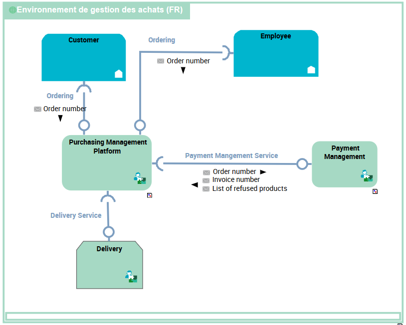
Application system environment diagram for the Purchasing Requests
Purchase requests are formulated by clients or employed using the "Purchasing Management Platform".
The "Purchasing Management Platform” application system uses an internal application system for the “Payment management” and a partner application system for the “Delivery”.
The elements of an application system environment diagram are:
• the main application system principal described by the environment.
• partner application systems that represent the other application system with which the main application system described by the environment interacts.
In this example, this concerns two loan services offered to individuals and companies.
• The categories of users of services provided by the environment are represented either by an Org-Unit or by a Position Type.
This concerns two user categories: individuals and companies.
• interactions between components
Creating an Application Environment Use Case Diagram
By means of use case, HOPEX IT Architecture V2 enables addition to description of an application architecture of the detailed specifications of its different sub-systems.
A use case diagram enables description of interactions between a system and actors of the organization.
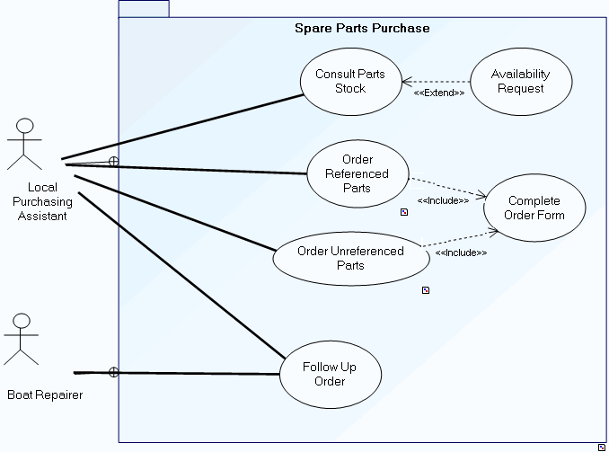
The system is used to consult parts in stock and to order new spare parts.
Consultation of parts in stock is carried out by the local on-site purchasing assistant. Following consultation, the assistant can make an availability request.
Two order types are possible, one for parts already referenced, the other for parts as yet unreferenced. In both cases, an order form should be completed.
Order follow-up is assured by the local purchasing assistant and the boat repairer.