Describing an Application Environment with HOPEX IT Architecture V2
Accessing the List of Application Environments
To access the list of application environments from the Application Architecture navigation pane:
The list of application environments appears in the edit area.
Creating an application environment
To create an Application environment::
1. From the Application Architecture navigation pane, select Functional Architecture > Application Environments.
The list of application environments appears in the edit area.
2. Click New.
The new application environment appears in the list.
Application environment properties
The Characteristics properties page of an application environment provides access to:
• its Owner, by default during creation of an application system environment, the current library.
• its Name,
• the text of its Description.
With HOPEX IT Architecture V2, an application environment is entirely described by a an application environment diagram that is used to describe the interactions between the environment applications described, its users and the external applications.
The following diagram describes the application environment corresponding to the processing of spare parts purchasing.
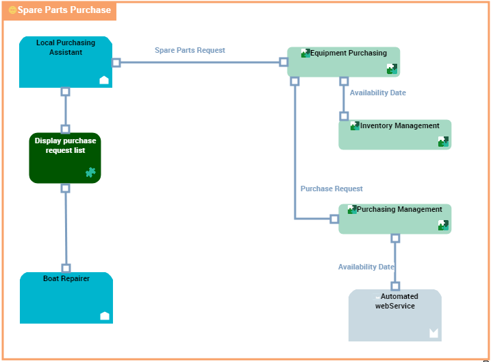
"Spare Parts Purchase" application environment diagram
The requests for spare parts are formulated by the persons concerned with boat repairs and these requests are processed by the local purchasing assistants.
Consultation of parts in stock is carried out by the local on-site purchasing assistant. Following consultation, the assistant can make an availability request.
Two order types are possible, one for parts already referenced, the other for parts as yet unreferenced. In both cases, a request for availability is put forth.
Order follow-up is assured by the local purchasing assistant and the boat repairer.
An application environment diagram includes:
• applications that represent the environment described.
In the example, this concerns the applications used for buying spare parts.
• applications, application services or partner micro-services that represent the external elements used in the described environment.
This example concerns automated Web services.
• org-units or type positions that represent the users or the suppliers of the environment described.
This example concerns local participants.
• interactions between components.
• access, request and service points
Creating an application environment use case diagram
To create a use case diagram from an application environment:
1. Right-click the application environment and click New > Diagram.
2. Creating a Application environment use case diagram.
The diagram opens in the edit window.