Using a Scenario of Application Flows Diagram
An Application Flow Scenario Diagram can be built for an application environment, an application, an Application System, an IT service or a micro-service. This diagram is used to describe the exchanges inside the described object in a specific context.
The scenario of application flow diagram below describes the "Purchase request management" application.
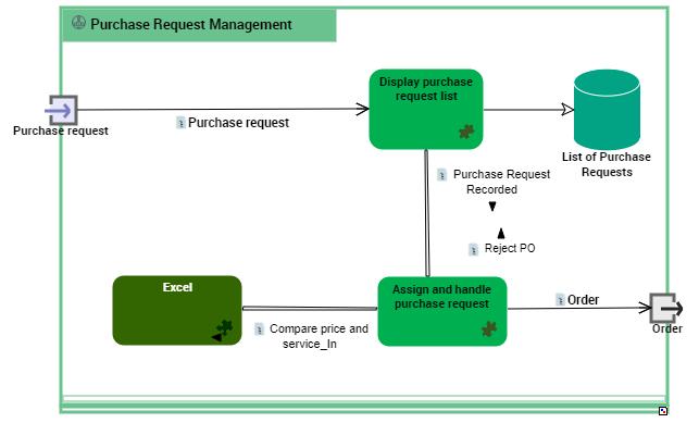
Example of a Scenario of Application Flows for "Managing Purchase Orders".
In a scenario of application flows diagram, the elements represented are:
• IT services,
• micro services,
• stores of internal or external application data,
• input or output application ports.
The interactions offered between these elements:
• application flows that carry a content,
• application flow channels that group a number of application flows on a single link,
• application data channels that represent the interactions between the application data stores.
Creating a Scenario of Application Flows diagram
To create a scenario of application flows:
1. Right-click the application and select New > Scenario of Application Flows.
2. (With HOPEX IT Architecture V2) in the window for choosing the diagram type, select Scenario of Application Flows.
Adding an IT service to the scenario of application flows
To add an IT service:
1. In the objects toolbar of the scenario of application flows, click Application.
2. Click in the described application frame.
A creation window box prompts you to choose the IT service implemented (for example "Customer management").
3. Select the application service required and click OK.
The application service appears in the diagram.
You can add a micro-service in the same way.
Managing application flows in a scenario of application flows
Creating an application flow with content
The application flows exchanged between the IT services, the micro-services or the Application ports of a scenario of application flows are associated with a content.
You must directly specify the content of an application flow directly on flow creation.
To create the application flow:
1. In the insert toolbar of the scenario of application flows, click Application Flow.
2. Click the first object representing the sender of the flow and, holding the mouse button pressed, draw a link to the object receiving the flow.
The Application Flow Creation dialog box opens.
3. In the Content drop-down list, select the content you wish to associate with the flow.
The application flow is displayed with its content in the diagram.
Creating an application flow channel
To create an application flow channel, you must first create the channel and then link the application flows that it groups.
To create an application flow channel:
1. In the objects toolbar of the scenario of application flows, click Application Flow Channel.
2. Click the first object in communication and, holding the mouse button pressed, draw a link to the other object.
The application flow channel appears in the diagram.
To connect the application flows to the application flow channel:
1. Open the Characteristicsproperties page of the application flow channel.
2. In the Grouped Flow section, click Connect.
A selection dialog box opens and presents the list of the ungrouped application flows of the scenario of application flows.
3. Select the flows that you want to group and click OK.
The application flow content appears with an arrow that marks the direction of the flow.
Reinitialize components in a scenario of flows
If you insert in a scenario of flows diagram a component that is already described by a scenario of flows, you can note that a new section is created in the Characteristics property page of the component you have added. This section allows you to specify which scenario of flows of the component corresponds to the context of the current application system scenario of flows.
In the component scenario of flows diagram, the Reinitialize components button allows you to insert components coming from the upper level scenario of flow.
Adding an application data store to the scenario of application system flows
A data store can be local or external to the application.
To add, for example, a local application data store to an scenario of application flows
1. In the scenario objects toolbar, click Local Application Data Store.
2. Click in the described application frame.
A creation window prompts you to choose the application data area that represents the physical structure that will concretely support the application data store.
3. Select the existing Application data area that interests you.
4. Click OK.
The local application data store appears in the diagram with the name of the physical data domain selected.
Creating an application data channel
The applications, the application systems and the micro-services can have read or right access to a local or external application data store.
To create an application data channel that represents a reading access:
1. In the diagram objects toolbar, click Application Data Channel.
2. Draw a link between the application data store and the object that reads the data.
An application data channel appears in the diagram.