Creating Operational Node Structure Diagrams
After creating your operational nodes the need for information exchange between operational nodes can be illustrated in the Operational Node Structure Diagram. This information exchange is represented by interactions created between the nodes. The diagram shows how operational nodes and interactions interact with each other.
An Operational Node Structure Diagram details the structure of an operational node. The node is composed of sub-nodes that are connected to each other through interactions.
The described node establishes a context for the interactions. For this reason sub-nodes are not directly connected in the diagram.
As sub-nodes can be reused in other contexts the interactions link the intermediate objects that reference the sub-nodes and that are defined locally within the context of the node. This way you can differentiate the interactions performed in one node context from those performed in another node context. In the case of operational nodes, the intermediate objects are called Operational Components. If no name is set for an operational component, a name is automatically created from the referenced operational node.
To create an operational node structure diagram:
1. In the NAF navigation tree click Operational Views > NOV-2.
2. Right-click the operational node concerned and select New > Operational Node Structure Diagram.
The new diagram opens with a Root Operational Node positioned in it.
Adding operational nodes to the diagram
Operational nodes in the Structure diagram are referred to as operational components.
To add an operational component to the diagram:
1. Click the Operational Component icon  in the object bar and click in the diagram.
in the object bar and click in the diagram.2. In the Add Operational node dialog box that appears, if you so desire, enter the name of the operational node.
3. Click the arrow to the right of the "Operational Node Used" field and select Connect Operational Nodes to find an operational node that already exists.
4. Click OK.
The new operational node appears in the diagram.
5. Repeat this step to create as many operational nodes as necessary.
Adding interactions to operational nodes
After creating your operational nodes you can display the interactions between them. Interactions describe the information that can be exchanged between two nodes.
An interaction links two interacting items and is based on a definition (a service definition): this definition can be detailed later on in the NSOV-2 view. See NSOV-2 Service Definitions.
The definition is used to accurately describe the information exchanged between the two nodes, the roles played by the two nodes (customer or provider) and the service and request points to which the interaction is connected.
To add an interaction to operational nodes:
1. In the object bar of the diagram, click the Interaction button 
2. Click the first operational node to be connected and holding down the mouse button, drag the cursor to the second operational node and release the mouse button.
3. In the Creation of Interaction dialog box that appears:
• select an existing service definition from the list
• (optional) enter the interaction definition name
4. Click OK.
A line representing the interaction appears in the diagram between the operational nodes.
The access points on interactions vary depending on particular situations.
• Turned out arrow: Consumer role is specified for the interaction
• Turned in arrow: Provider role is specified for the interaction
• Square: No role is specified
• Empty square or arrow: no access point is specified for the service
• Full square or arrow: an access point is specified for the service
Adding content to interactions
It is possible to add and display the content of interactions in the different structure diagrams.
The information elements (contents) exchanged in an interaction are defined in a service definitions (shared interaction protocols).
Content must be added in this definition and impacts all the interactions based on it.
To add content to an interaction:
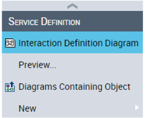
1. Right click the name of the interaction.
2. In the pop-up menu that appears select the service definition > New > Interaction definition diagram.
3. Create a message of Request type from the Consumer to the Provider.
4. Select or create a content and click OK.
A new message appears in the Interaction Definition Diagram.
Below is an example of an operational node structure diagram. The operational nodes are represented by yellow rectangles.
Example of an Operational Node Structure Diagram (no content displayed)