Creating Activity Models
The entry point for the operational activity models is the functional process concept. Functional processes describe a sequence of transformation activities. To describe a functional process, you can use the Functional Process diagram. This functional process can then be broken down to reveal the different activities of the process.
The Functional Process diagram contains the activities that can be assigned to operational nodes (see figure below). The details of an activity can then be further described in another Functional Process diagram. This is how a hierarchy of activities is to be generated.
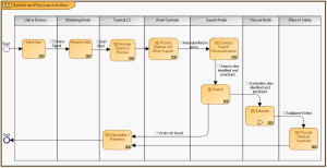
The figure below is an example of a Functional Process Diagram. It displays the Search process of the architecture. In this figure the process contains activities that are assigned to different operational nodes.

Note that activities can sometimes call different processes. See the
HOPEX Business Process Analysis user guide for more information on creating process diagrams.
Example of a Functional Process diagram
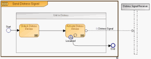
The figure below shows the details of the Send Distress Signal activity through another dedicated Functional Process diagram. In this figure, the described activity contains two sub-activities.
A Detailed Illustration of the NOV-5 Send Distress Signal Activity
To create the "Functional Process Diagram":
1. In the NAF navigation window, expand the NOV-5 Operational Activity Model and Root Functional Pocesses folders.
2. Right-click the functional process for which you wish to create the diagram and select New > Diagram > Functional Process Diagram > Create.
A diagram opens in the desktop, on the right with a frame representing the functional process to be described.
Participants
As you will have noticed, you can place your participants inside as well as outisde of the process on which the Functional Process diagram is based. The participants placed on the outside of the process should not have activities placed on them. The purpose of the participant is not to describe activities but to help detail the external interactions of the process.
Adding participants to the Functional Process diagram
Before you place a participant in a diagram, you must first create the paticipant and assign it to an operational node or operational component. When this is done, only the assigned component or node can be attached to this participant in the diagram.
It is more accurate to assign an operational component than an operational node to a participant. This is so as operational components are already defined in particular contexts.
Activities
Activities are added to the participants in the diagram to indicate the steps in the process.
To add an activity:
1. In the objects bar select the Functional Activity icon and click in the diagram, on the participant responsible for the activity.
2. Enter the name of the functional process and click OK.
The new activity appears in the diagram.
If the activity represents another functional process, you can call this process from within the
Properties dialog box,
Characteristics tab, "Called Functional Process" box. Note the shape difference between activities with and without called processes.
You can describe your activities in detail through Activity Decomposition diagrams.
Events
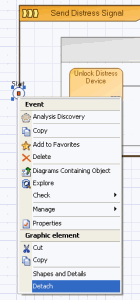
When you add events to your diagram (Start End, etc.), you may choose to place them in the process or on the frame of the Process described by the diagram: this can be done through a drag and drop motion. If you place the event on the frame, a red rectangle appears in the event.
The event cannot be returned to the inside of the process with a drag and drop motion.
To remove the event from the frame and place it inside the process:

Right-click the event and in its contextual menu, select
Detach.
You can then drag and drop the event into the frame.
Message
Messages are used to pass on information from one element to another. This exchange of information in the process diagram is displayed in message flows through the use of the message flow icon.
Sequence
The activities in a process are not all carried out simultaneously. Often the execution or completion of one activity triggers or leads to another activity. Sequence flows are therefore used to indicate the steps to be followed (sequence of activities) in a process. The sequence flows of activities are indicated through the use of the sequence flow icon.
Messages are also sent from one activity to another and, as mentioned before, are represented through the use of message flows.
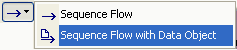
If you so desire, you can combine the sequence of activities with the exchange of information between these activities. This can be done through the use of the "Sequence Flow with Data Object" icon.
To create a sequence flow with message content between two activities:
1. In the objects menu bar click the arrow of the Sequence Flow icon and select Sequence Flow with Data Object.
2. Click on the activity where the flow begins and holding down the mouse button, draw a line to the activity to be linked.
Lines are drawn in the direction of the flow.
3. Release the mouse button.
The sequence flow normally starts from an event, for example, Start.
4. Create a new content or find an already existing one and link it to the sequence flow.
5. Click OK.
A line with an arrow appears in the diagram between the two activities. The name of the attached content appears next to the line. The arrow indicates the direction of the sequence/message flow.